Powering up
To start HiPERCAM from cold, the following operations must be performed. This guide assumes that HiPERCAM has been mounted on the telescope focus and is cabled up. Click on the photos below for larger images.
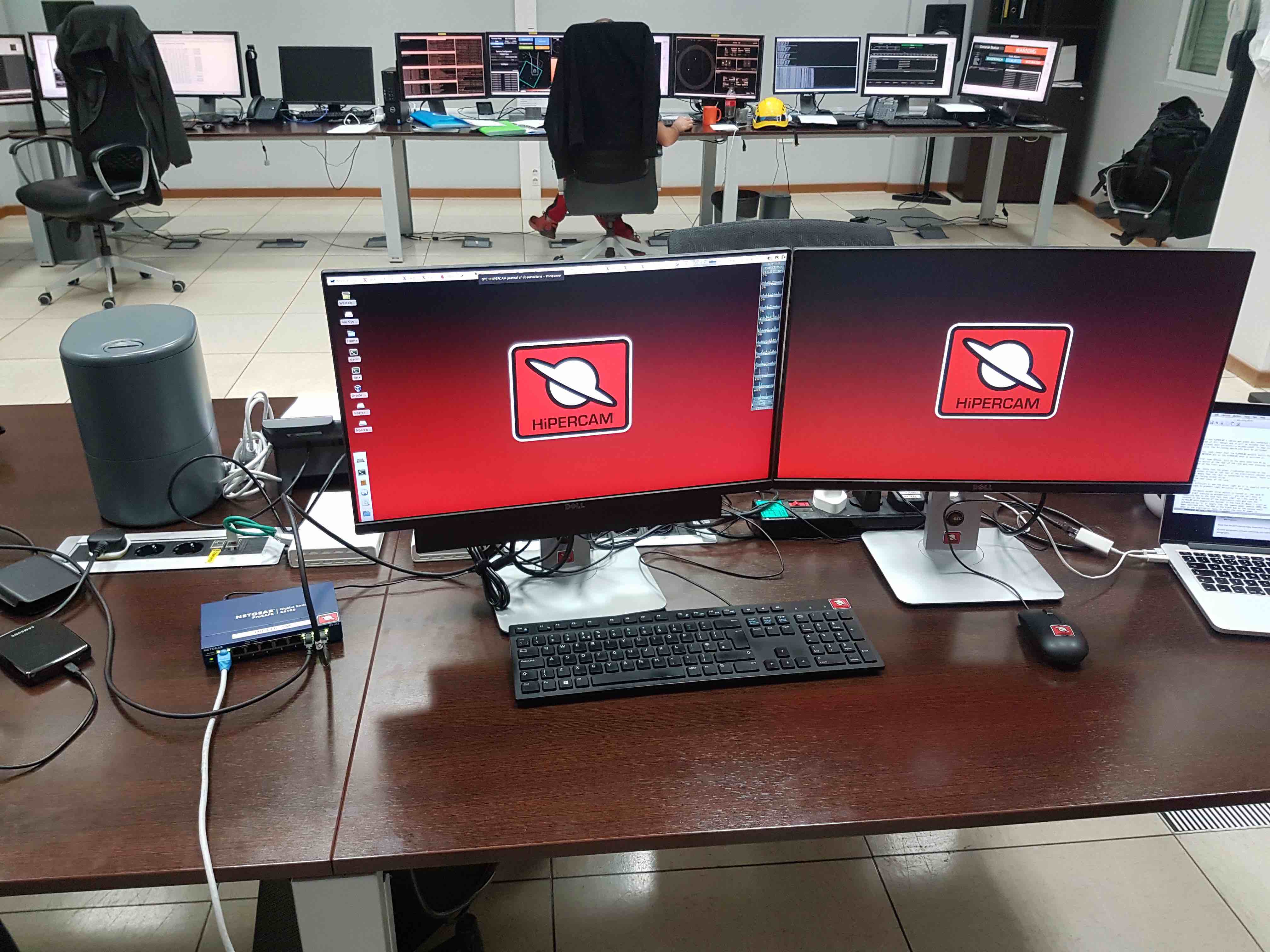
In the control room, check that the blue HiPERCAM ethernet switch, the two HiPERCAM monitors and the speakers are switched on.
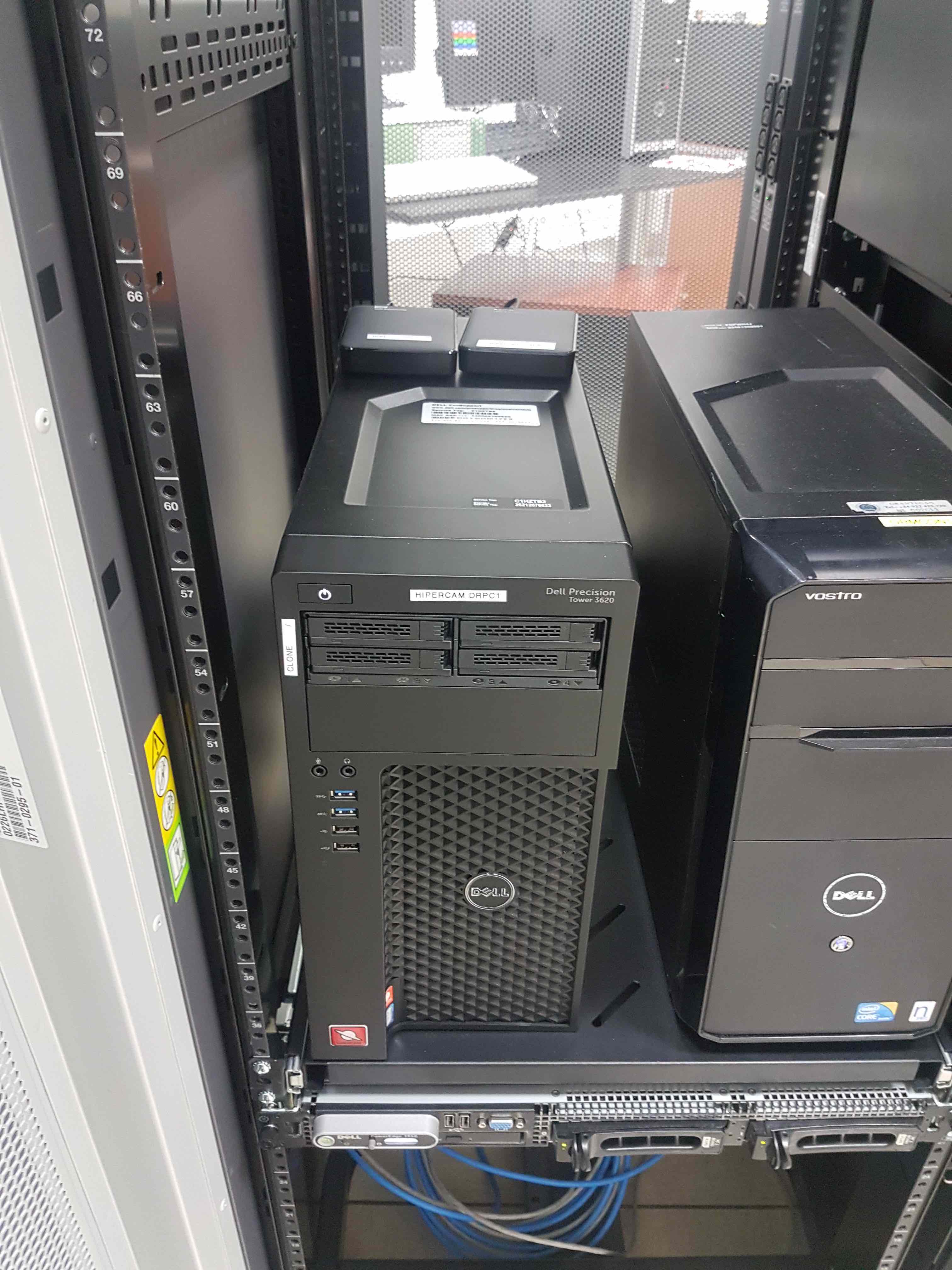
If the HiPERCAM data reduction PC (DRPC) is not powered on, go into the control room annexe and press the power botton on the upper left-hand side on the front of the case. Ensure that there are two USB disks connected to the DRPC - if not, you can find new ones in the crates.
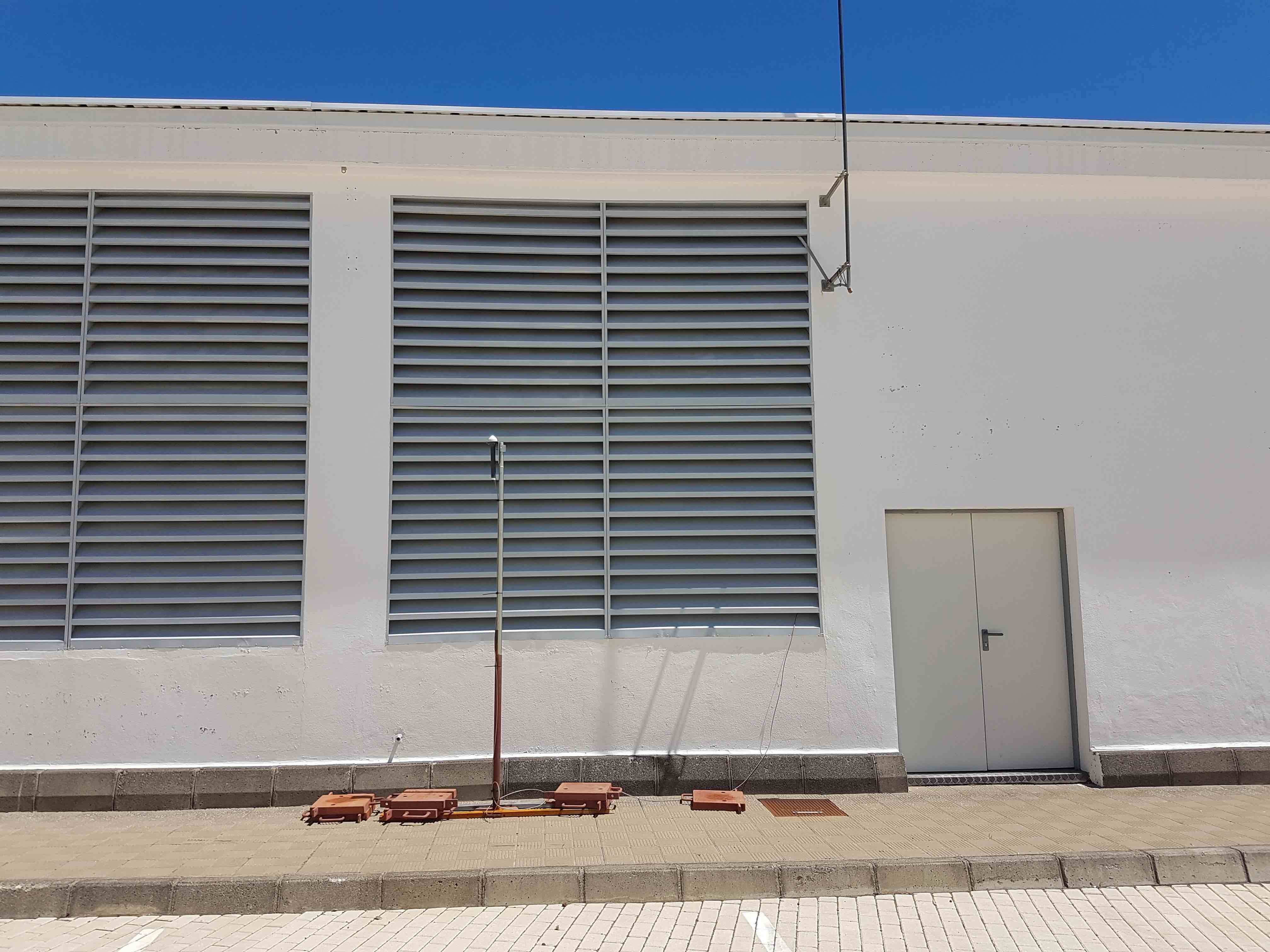
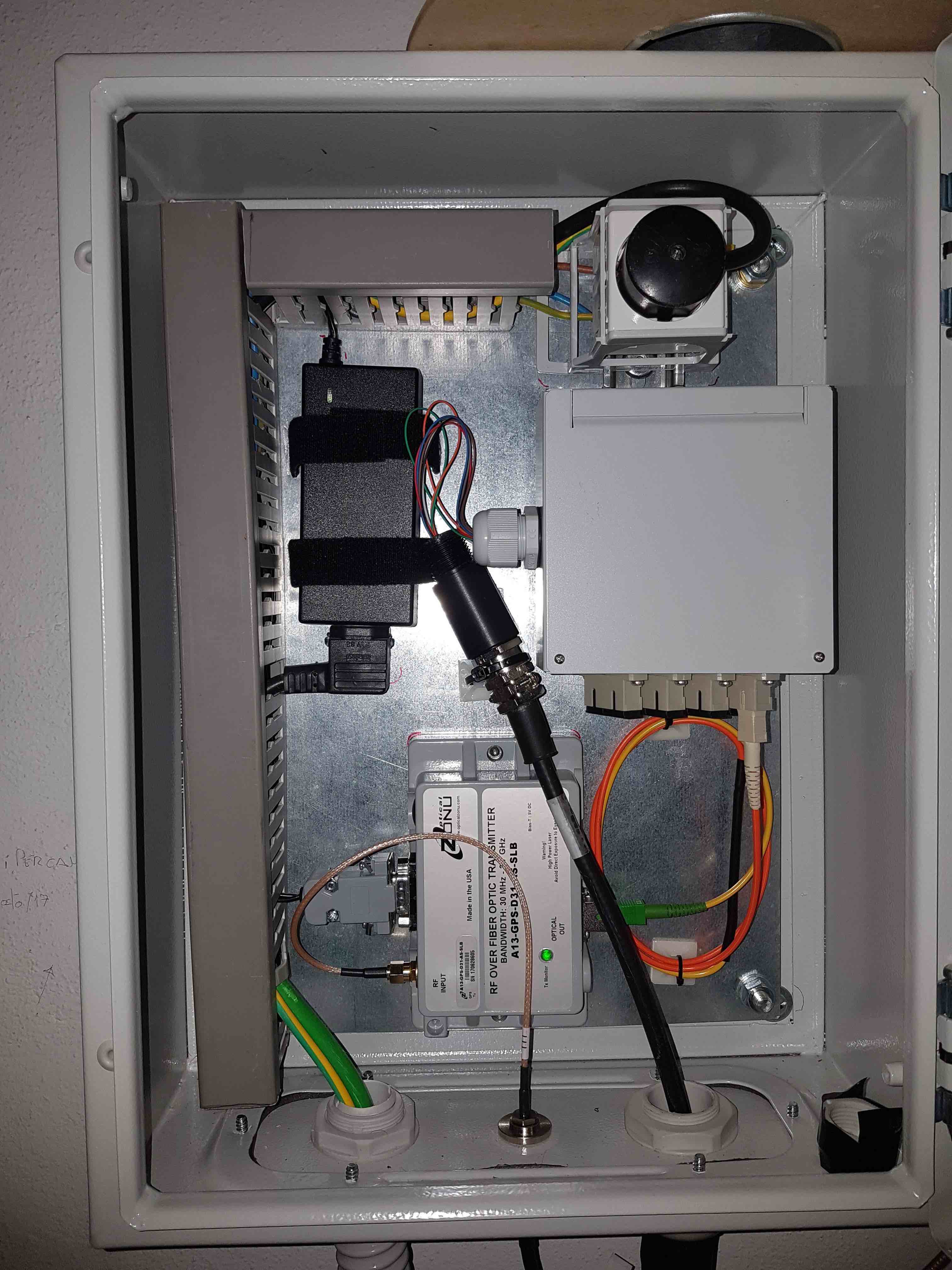
In the GTC annexe building, plug in the black euro mains power plug in the top right-hand corner of the HiPERCAM GPS wall-mounted cabinet, located to the left of the entrance door when looking outwards. You may need to ask a member of GTC staff to unlock the entrance door for you.
Prior to going up to the elevation platform, follow the safety instructions given in pumping and cooling. In summary, you must be qualified to work on the platform, you must put on your safety gear, take a radio, and inform the GTC Jefe de Turno (during the day) or Telescope Operator (at night) that you are going up to the instrument.
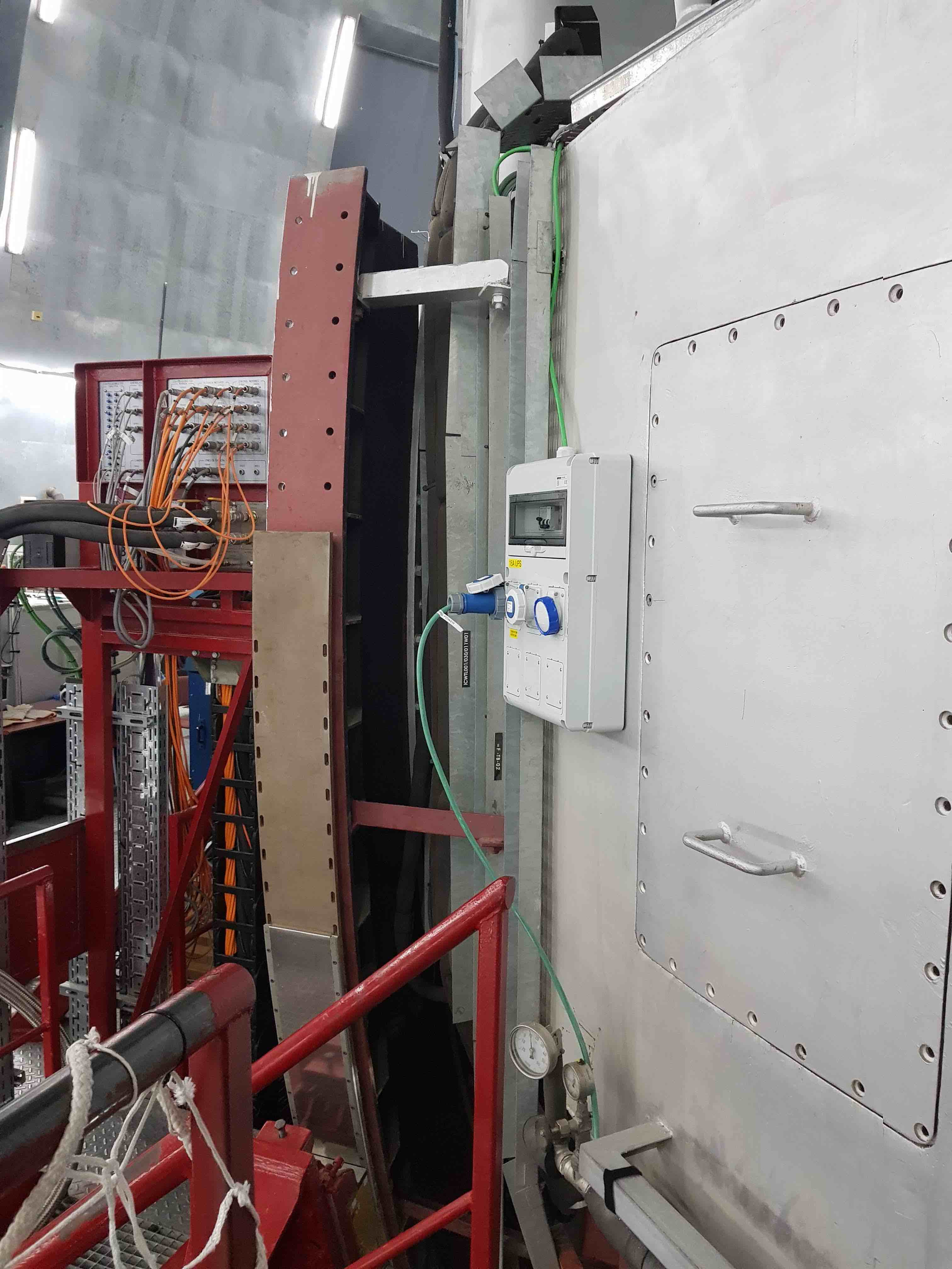
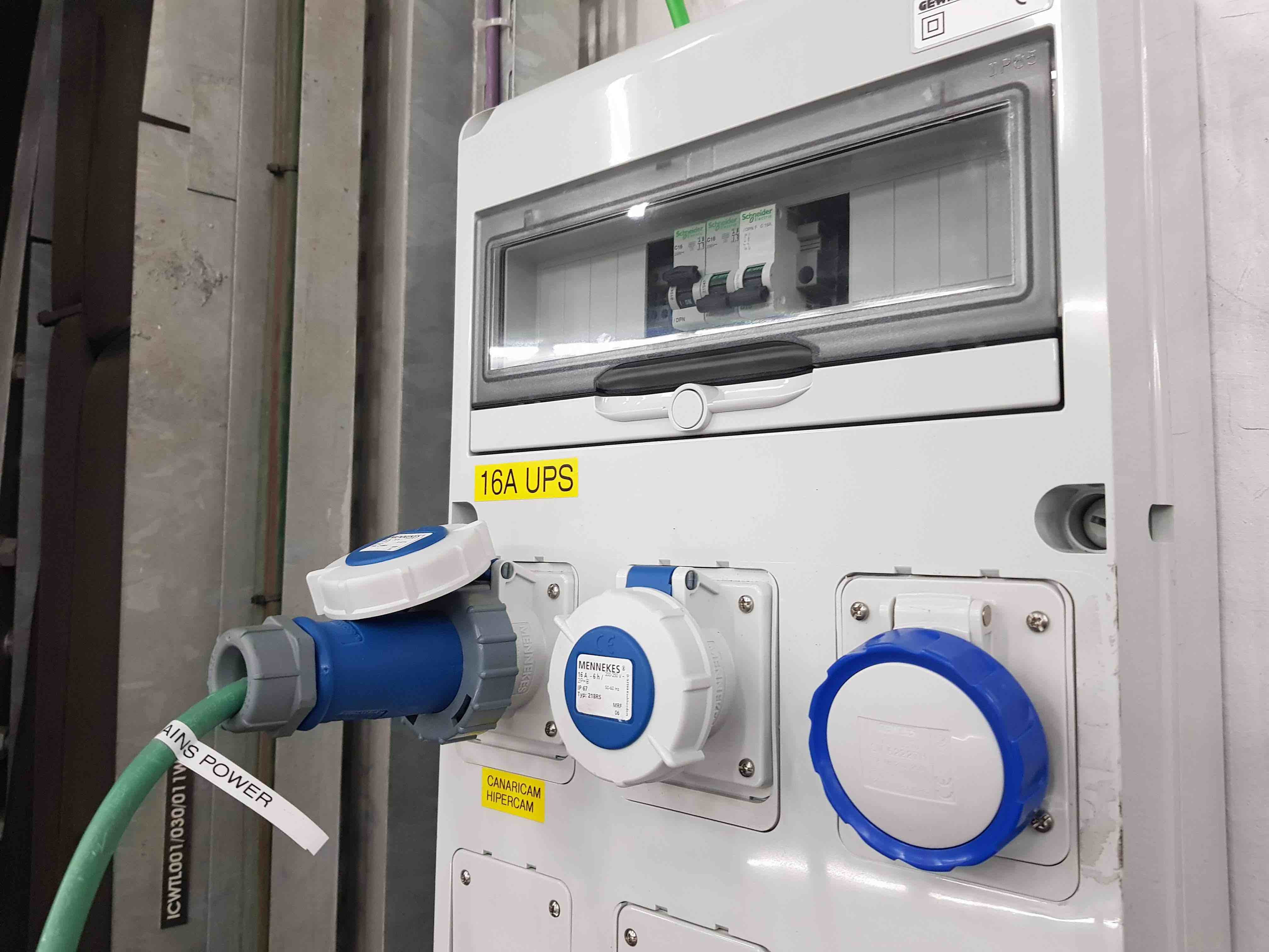
Check that the UPS mains power cable from the HiPERCAM cabinet is plugged into the left-hand socket of the wall-mounted box near the stairs from the Nasmyth platform. Ensure that the left-hand circuit breaker above the socket is switched on.
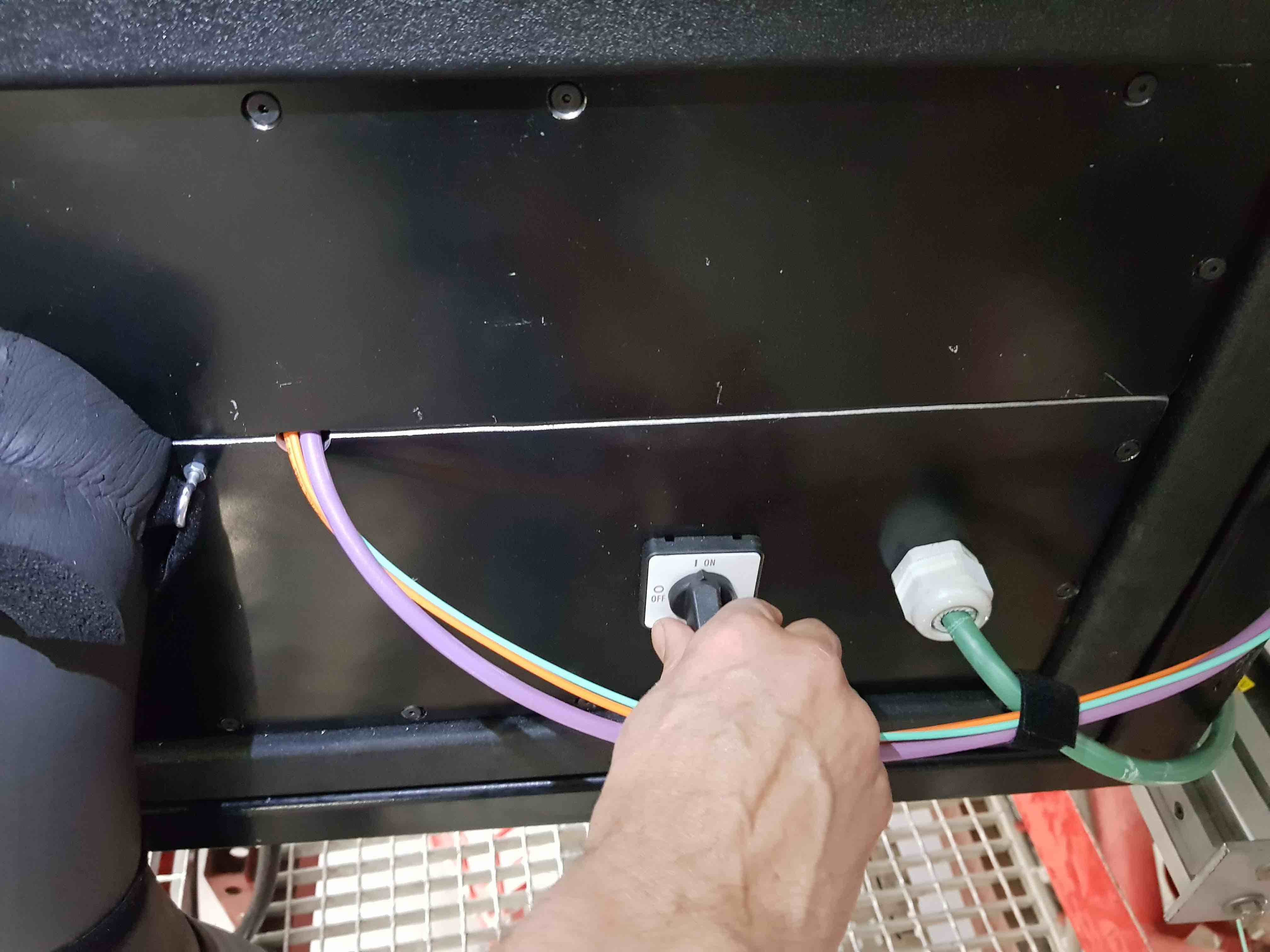
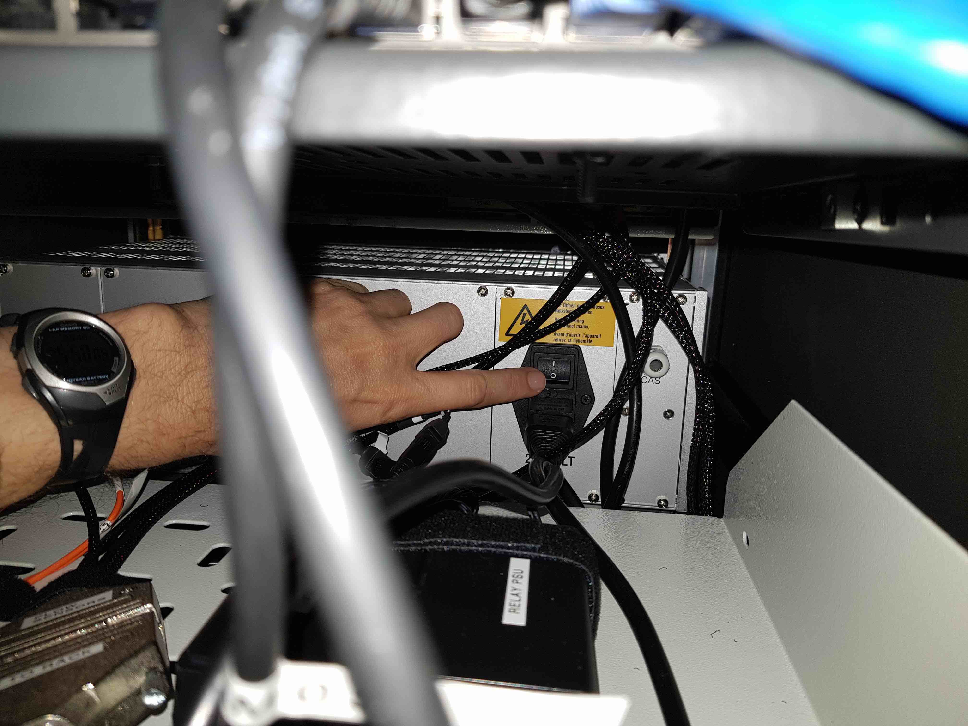
Turn on the power to the whole cabinet using the external switch at the bottom of the rear of the cabinet.
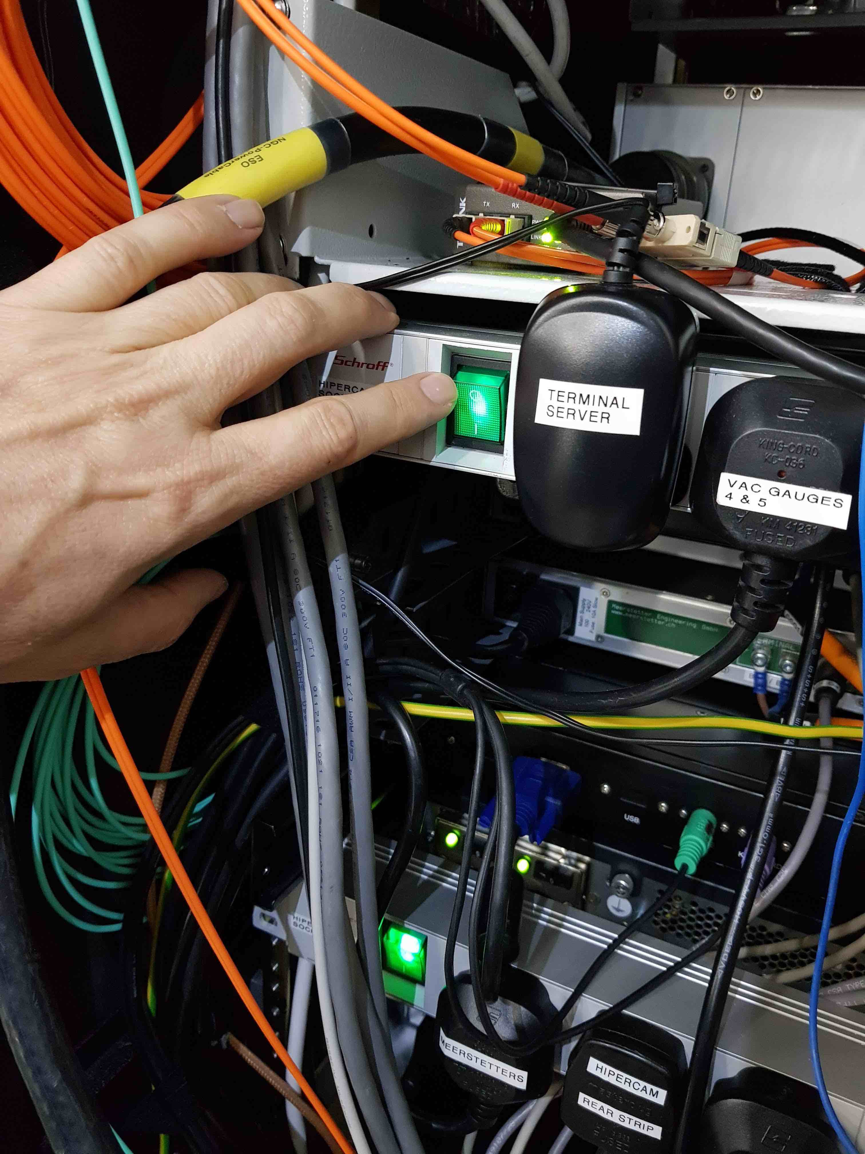
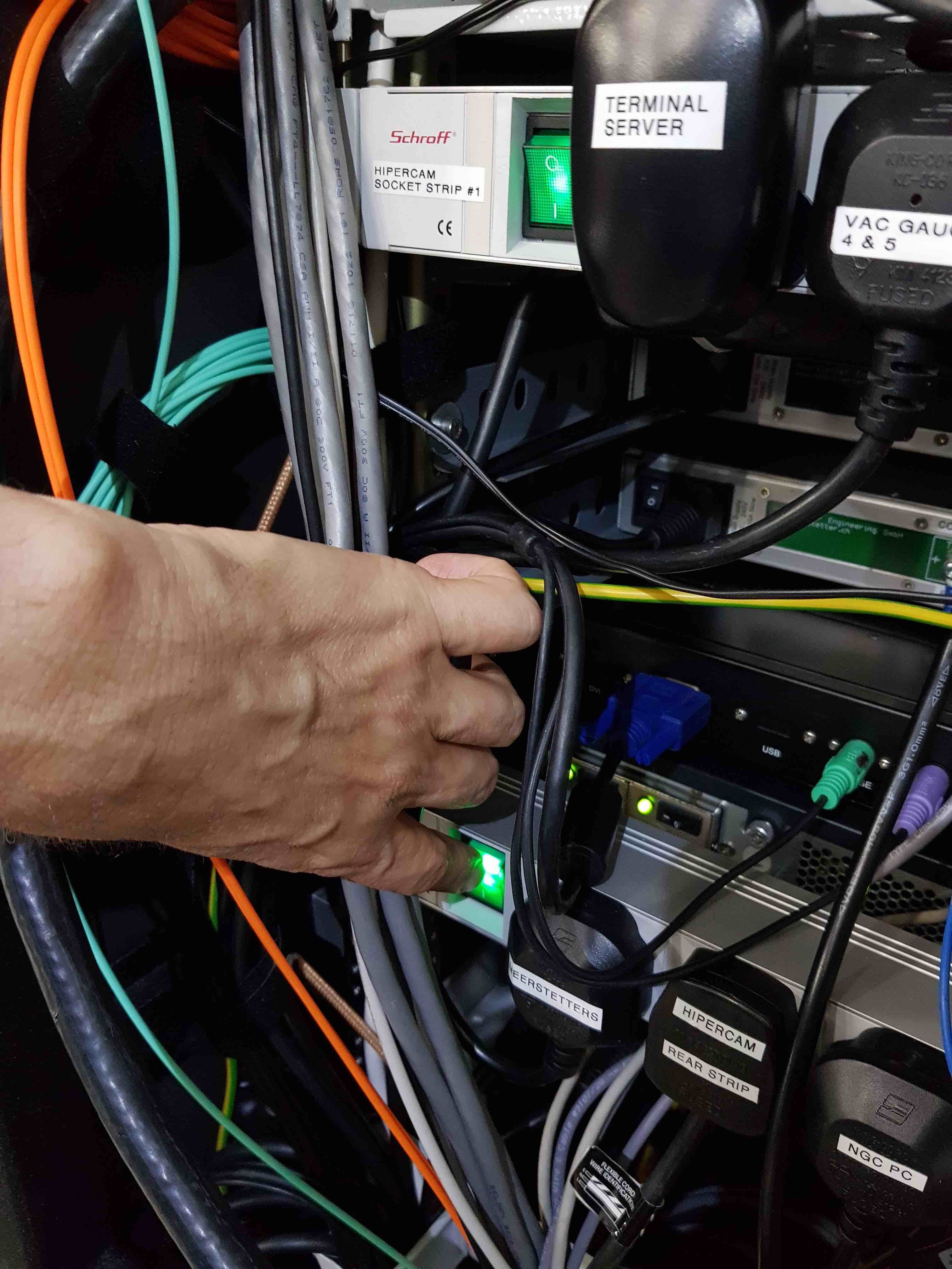
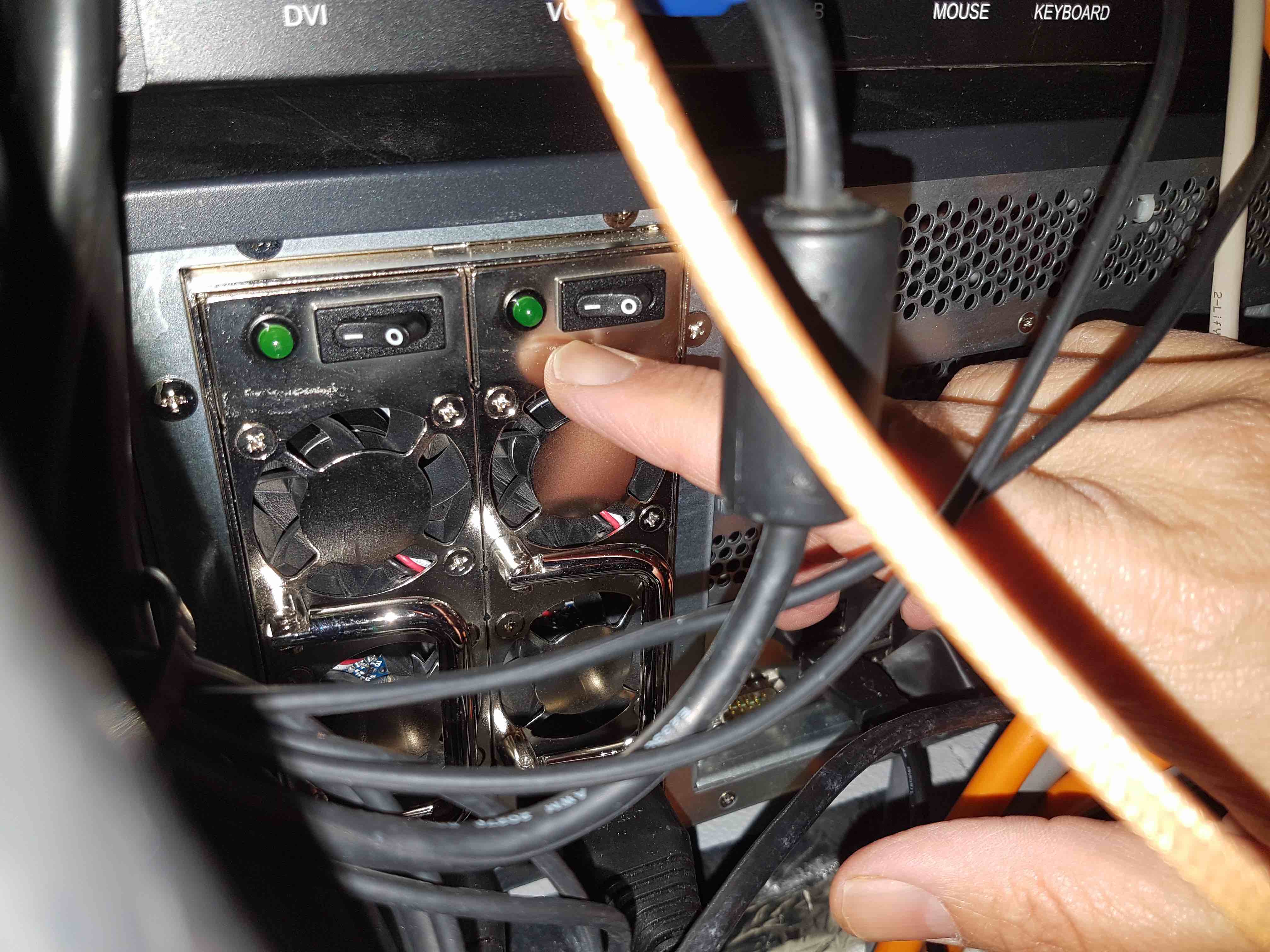
Turn on the three internal socket strips by pressing the two green switches on the left-hand side of the two rear-facing sockets strips at the rear of the cabinet. These switches will illuminate when powered on, and the third (internally-facing) socket strip will be turned on automatically.
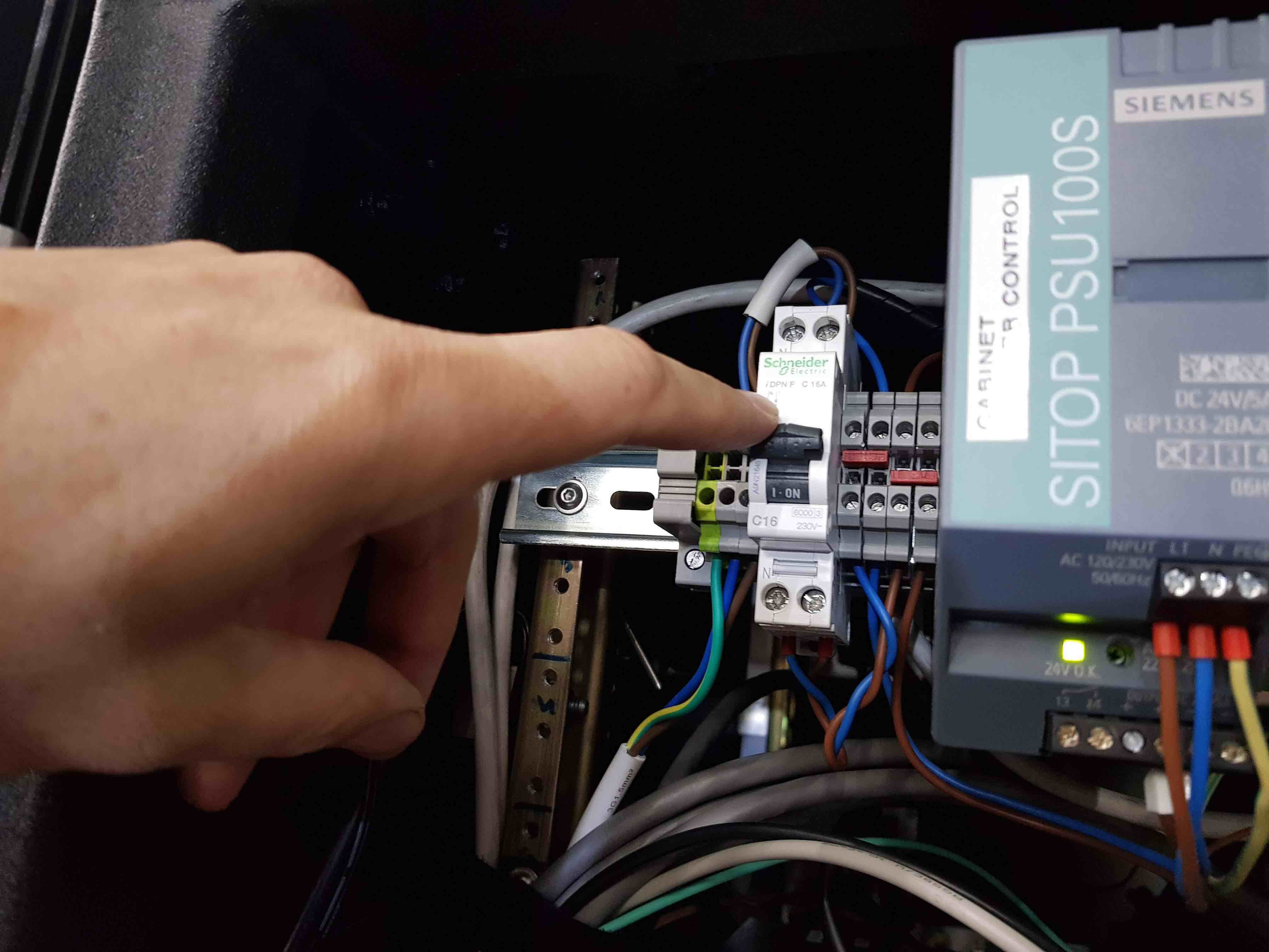
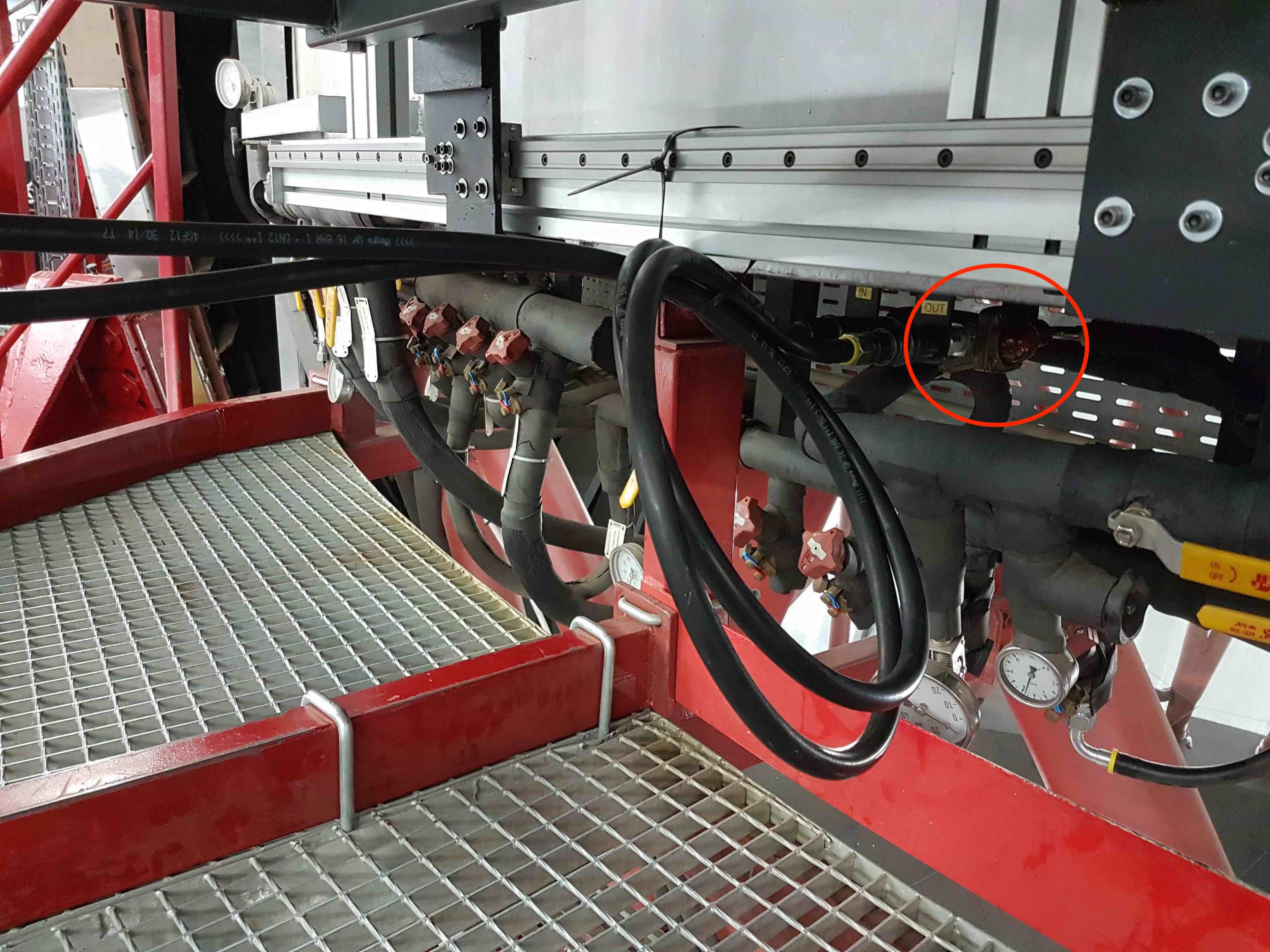
Turn on the cabinet chiller by pushing the switch up on the left-hand side of the DIN rail at the top of the rear of the cabinet. Check that the coolant is flowing through the cabinet by inspecting the flow indicator shown in the photo below. If the red propeller is not spinning, ask a member of GTC staff to turn on the coolant flow. If it still does not spin, it is possible that the electromagnetic valve in the chiller unit mounted on the side of the cabinet is closed due to the cabinet temperature being below the set point at which the chiller turns on. In this case, ask a member of the GTC staff to lower the temperature limit of the cabinet in order to open the chiller valve - this can be done from the control room. You should now see the propeller start spinning and feel cold air coming into the cabinet through the vent at the bottom of the side wall.
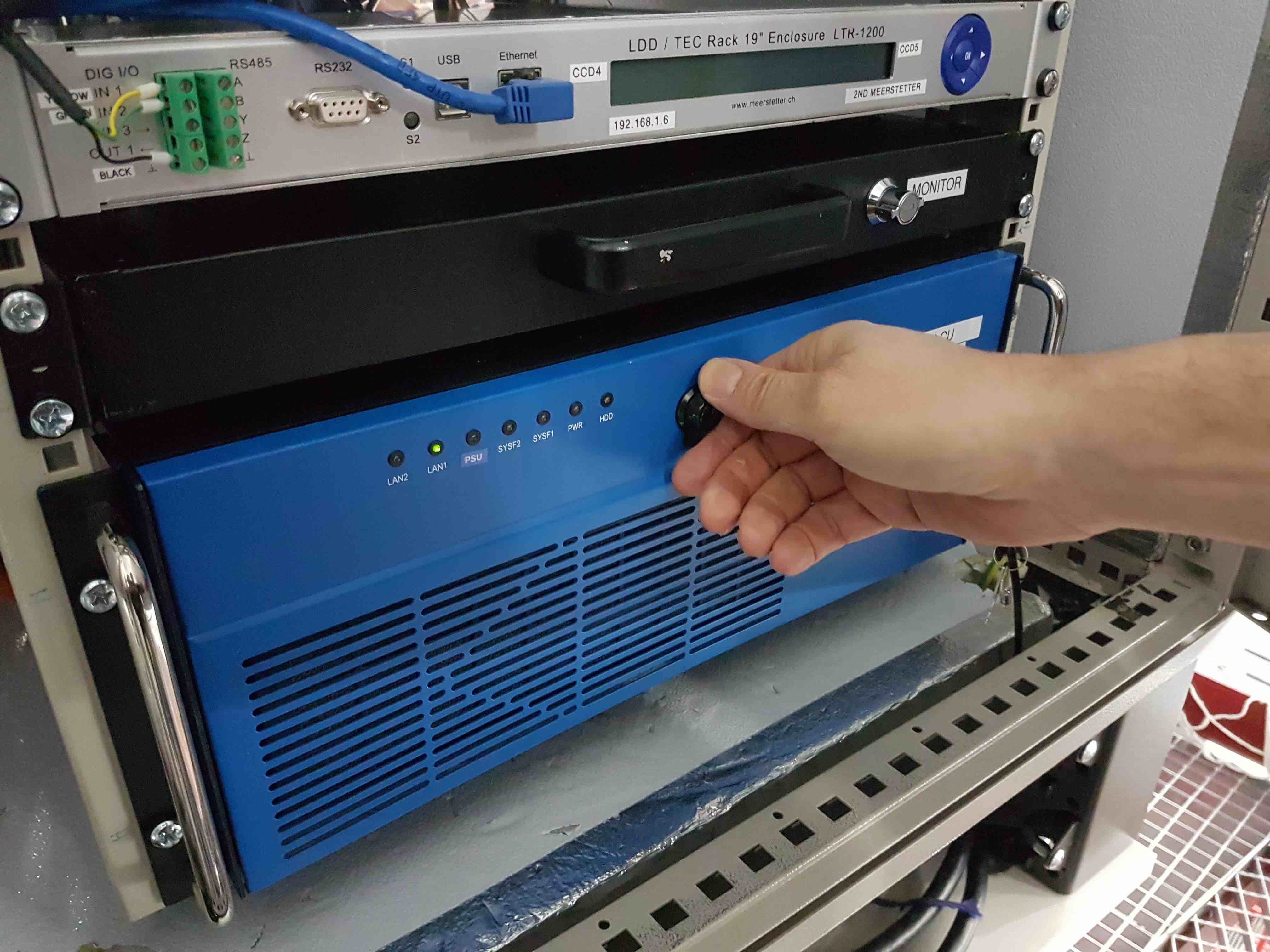
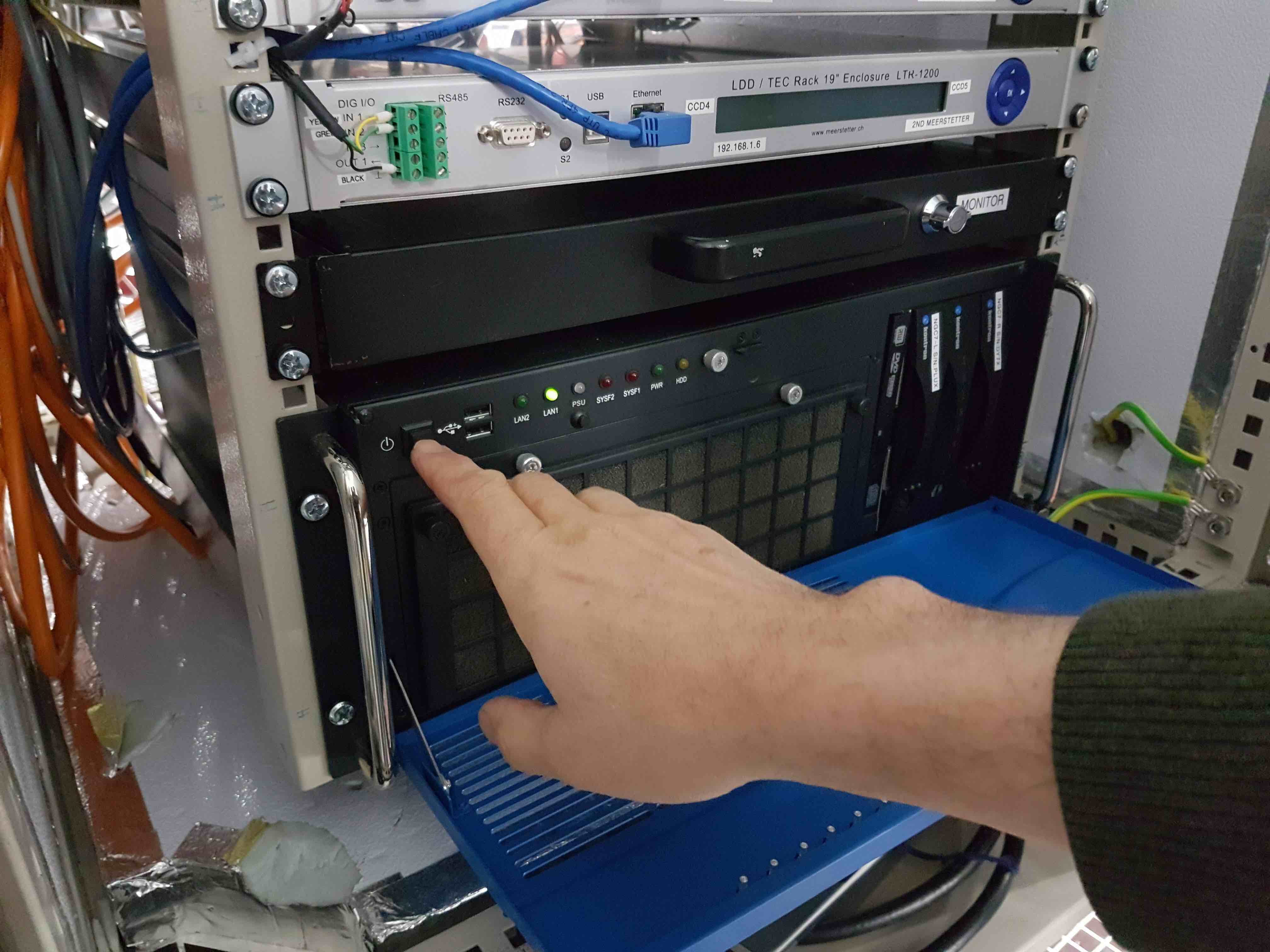
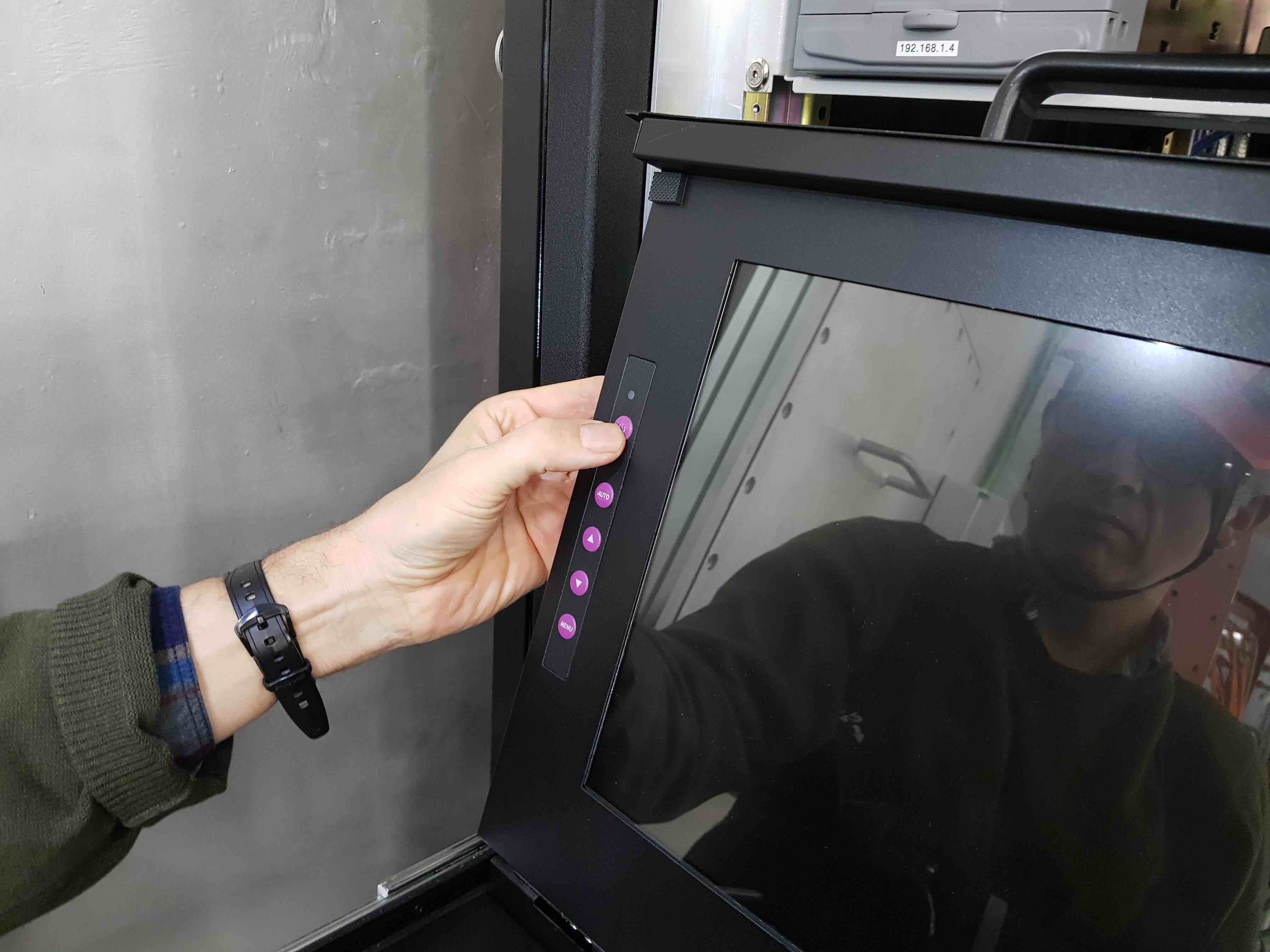
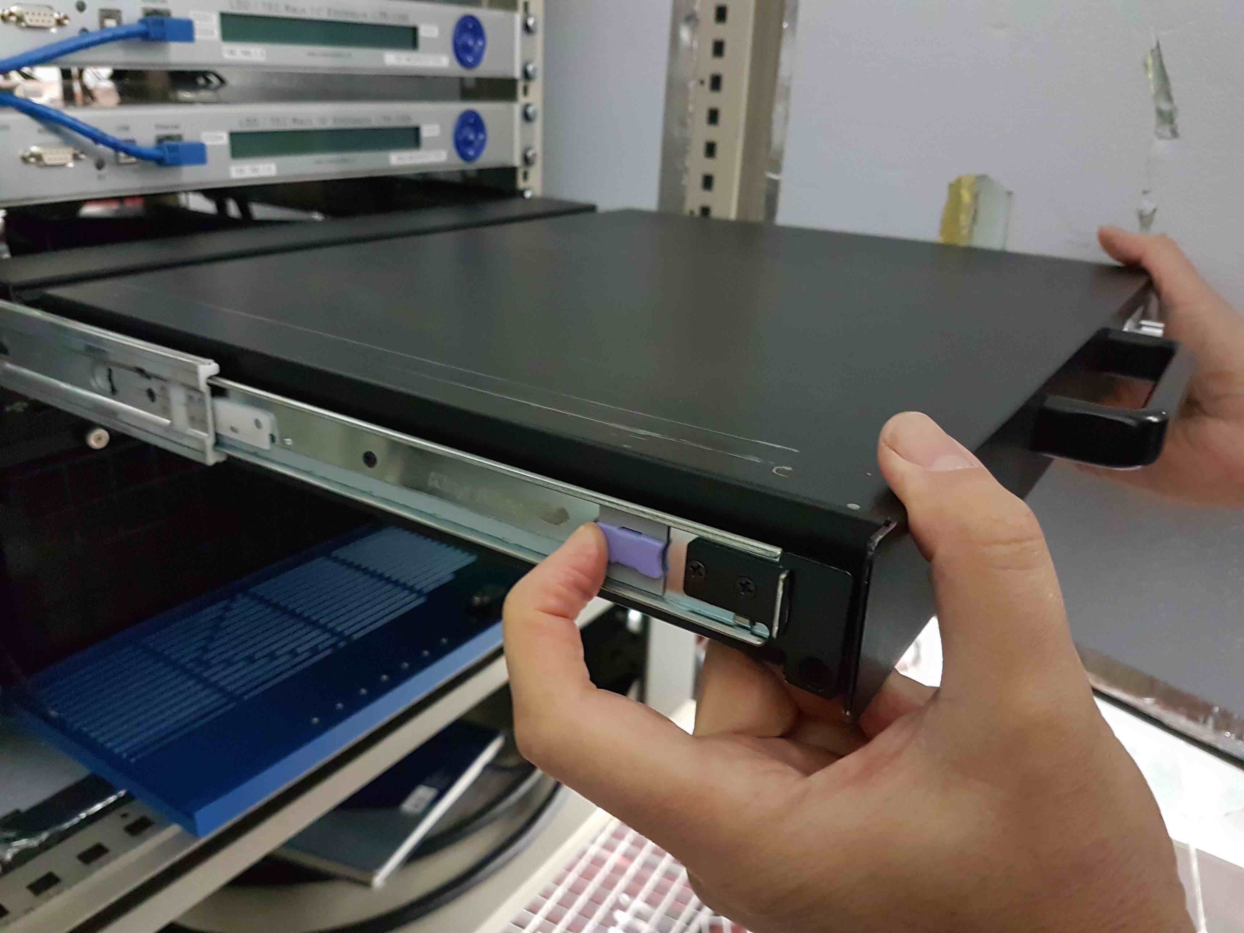
Turn on the rack PC. First, switch on the two PC power supplies on the rear-left of the unit. Then open the front door of the rack PC and press the power button on the left-hand side. Next, slide out the monitor/keyboard/mouse by twisting the lock and pulling, and power them on using the button on the upper left-hand side of the screen. Wait for the rack PC to boot, which will take a few minutes. To slide the monitor back into its housing, you have to pull the two blue release catches on the side rails on either side of the monitor.
Log into the rack PC as user
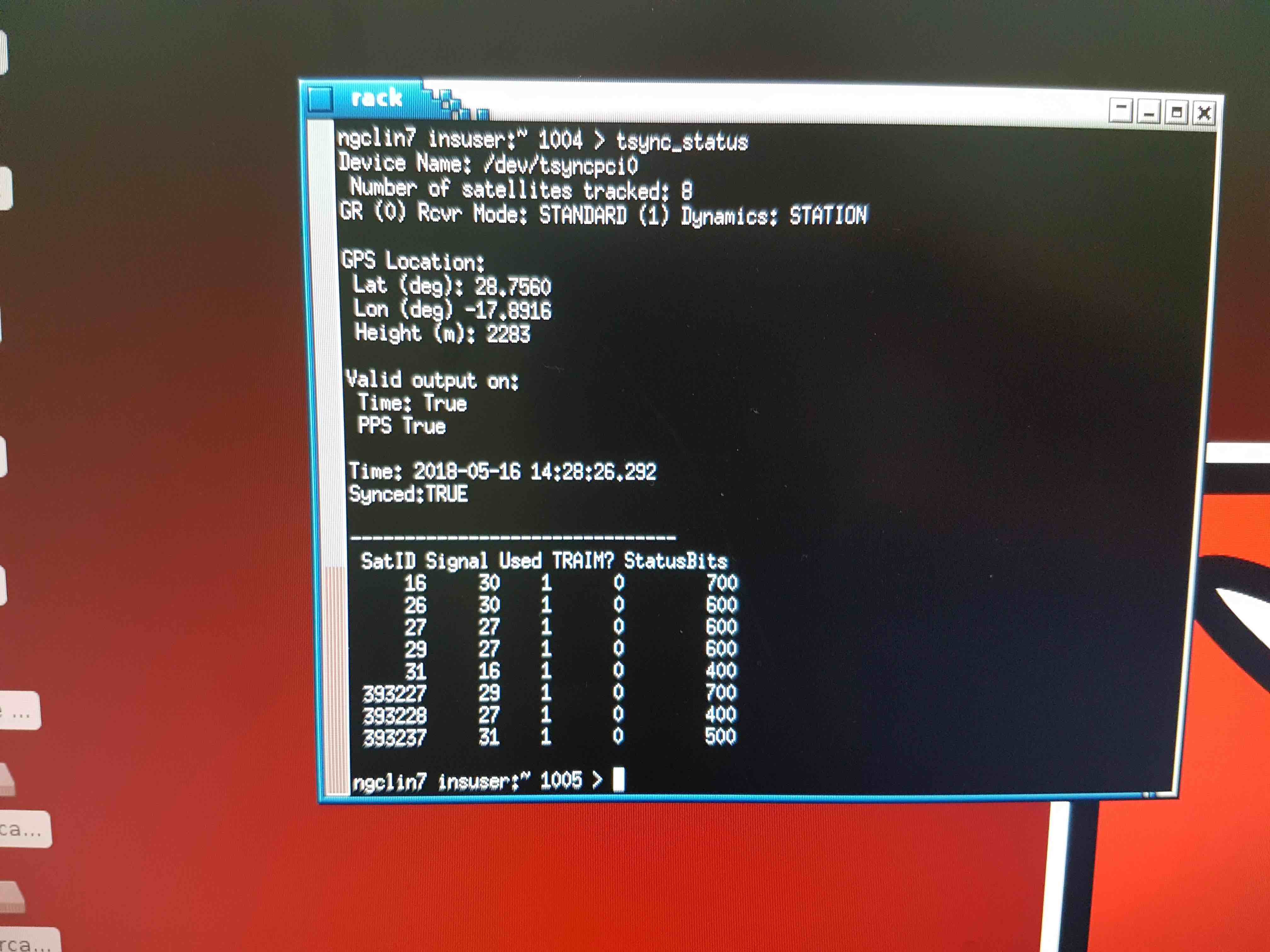
insuser. If you need to know the password, please contact one of the HiPERCAM team members.When the window manager has started up on the rack PC, open an xterm and check that the GPS antenna is working by typing
tsync_status. Check that all statuses are True and that 4 or more satellites have been detected.
In the same xterm, check that the internal ethernet connection between the rack PC and the DRPC is working by typing:
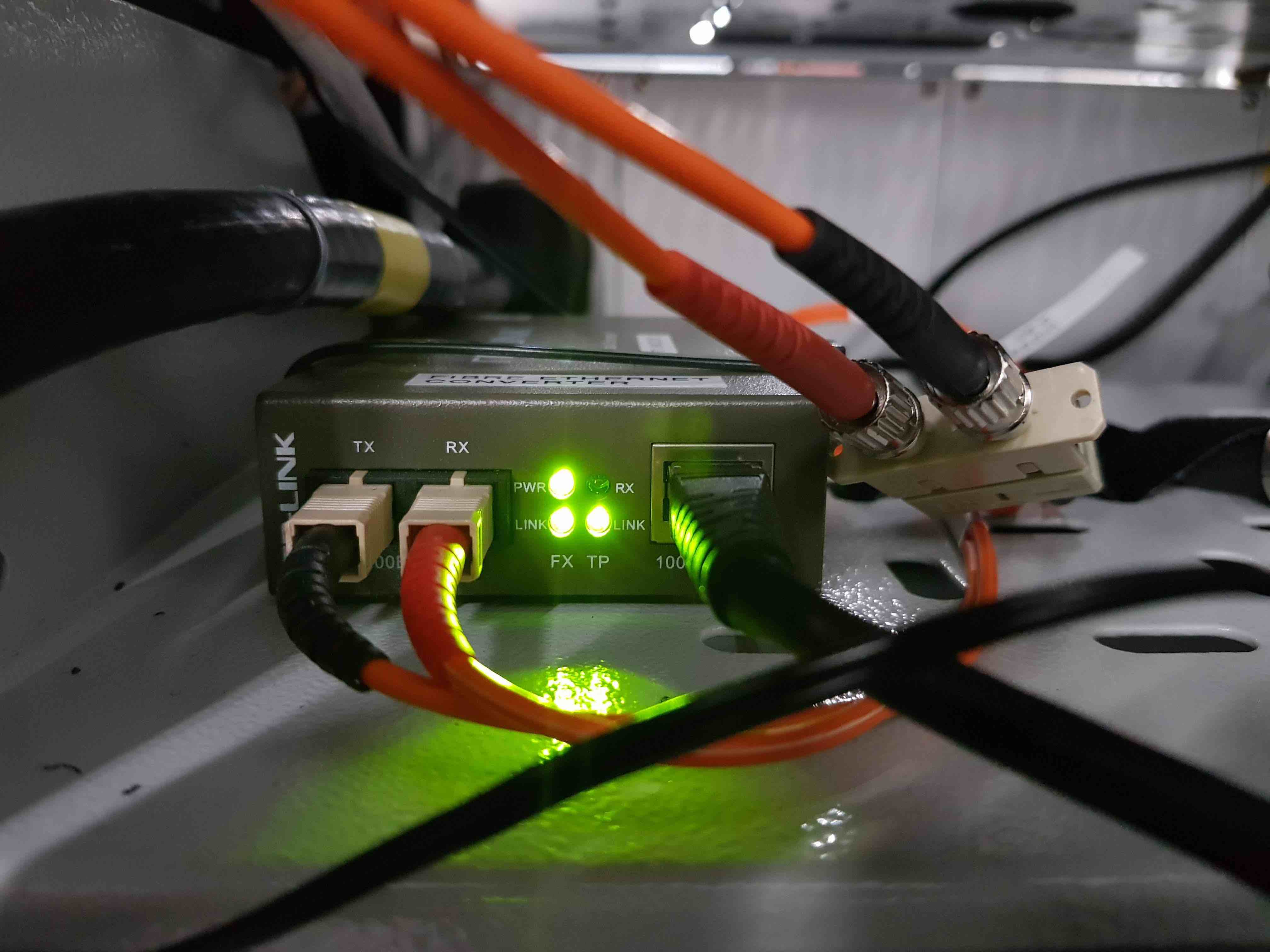
ssh observer@192.168.1.1. If you can’t log into the DRPC, check that all 4 green LEDs are illuminated on the fibre-ethernet converter at the rear of the cabinet.
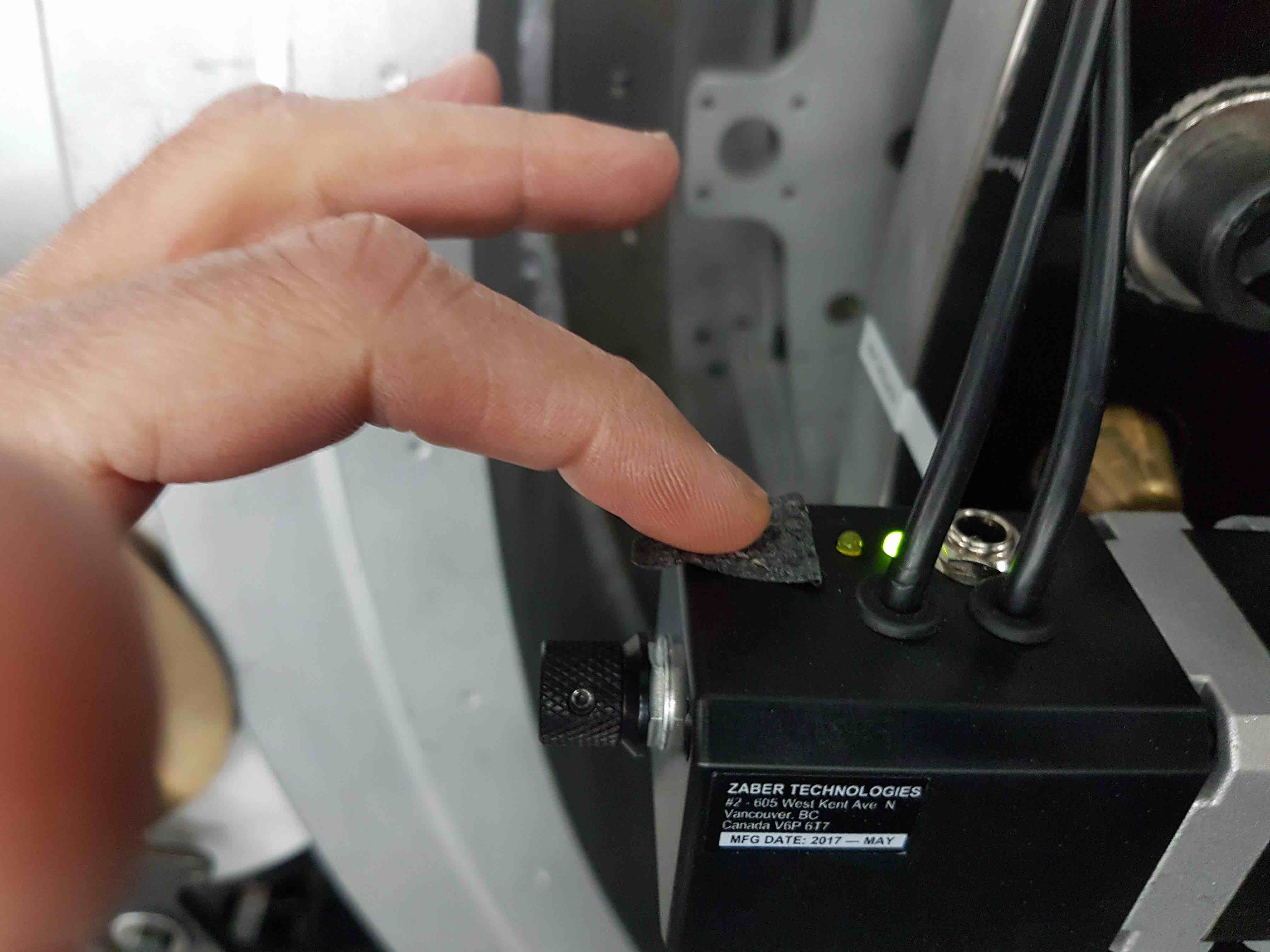
In an xterm on the rack PC, check that focal-plane slide is working. First, start the hardware server by typing
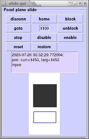
hwserver
&
. Then home the slide by typingslide_eng home, followed byslide_eng positionto verify that the slide has homed. Then typeslide_eng move 1000to verify that the slide moves 1000 microsteps. If the slide does not move, verify that the green power LED under the black tape on the motor is lit, and try power cycling the slide by disconnecting and connecting the connector on the slide. Once the slide is working, close down thehwserverby typingfgand thenctrl-cin the same xterm.Alternatively, you can use the slide engineering GUI by typing
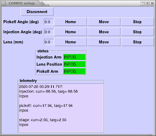
slidein an xterm on the rack PC. You don’t needhdriverto be running for this to work, although you do need the hardware server up. Similarly, there is a COMPO engineering GUI that can be started by typingcompo_guiin an xterm on the rack PC.
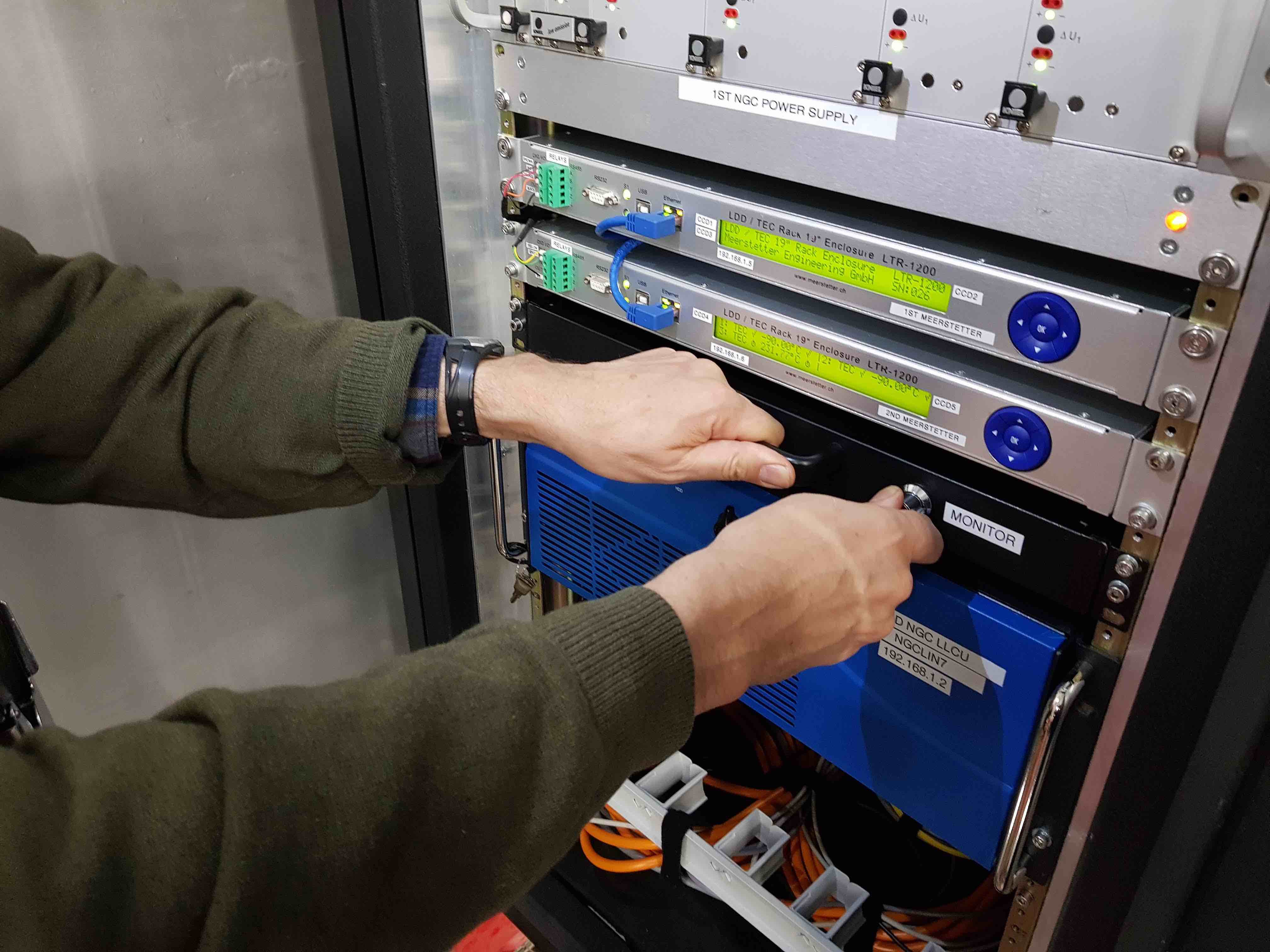
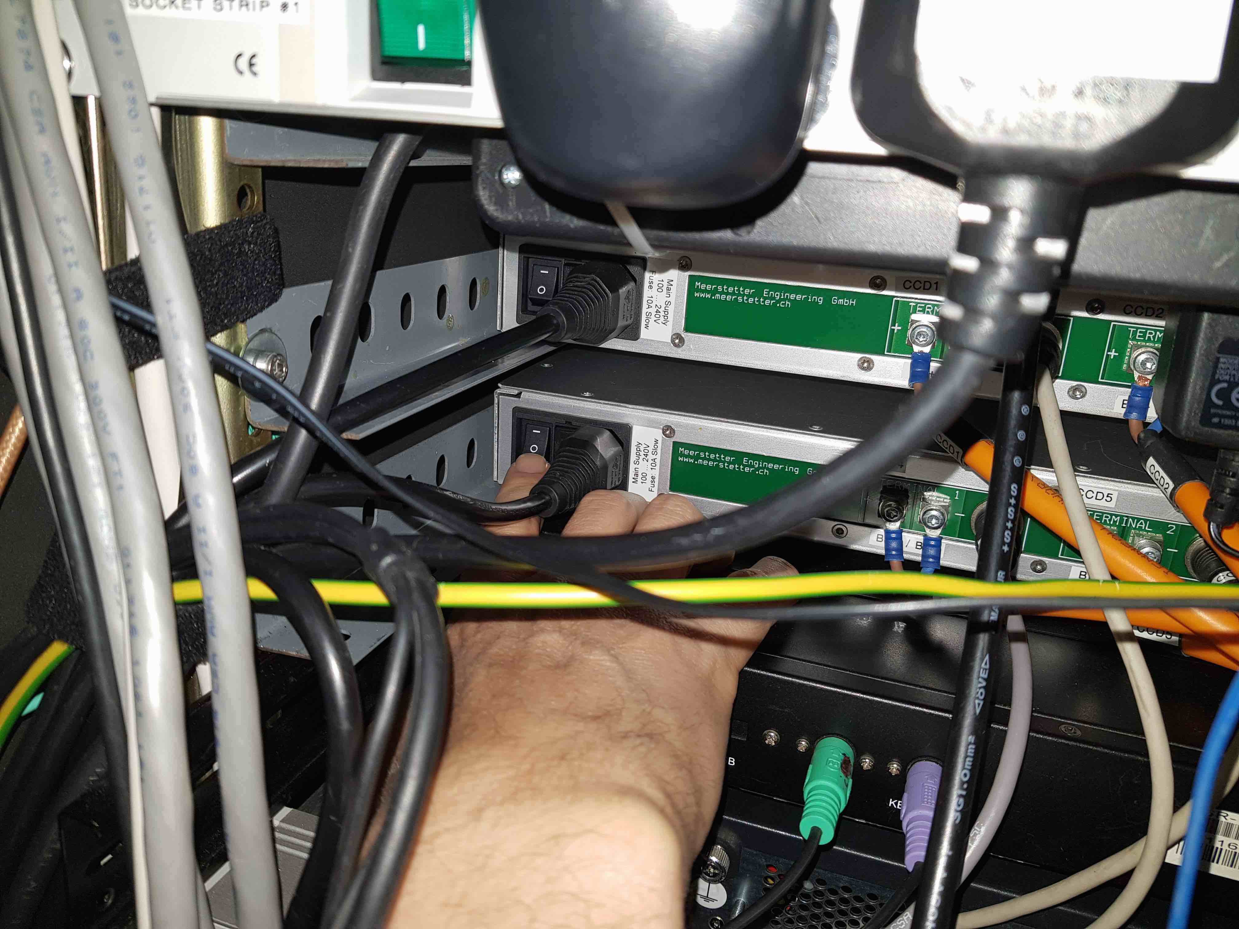
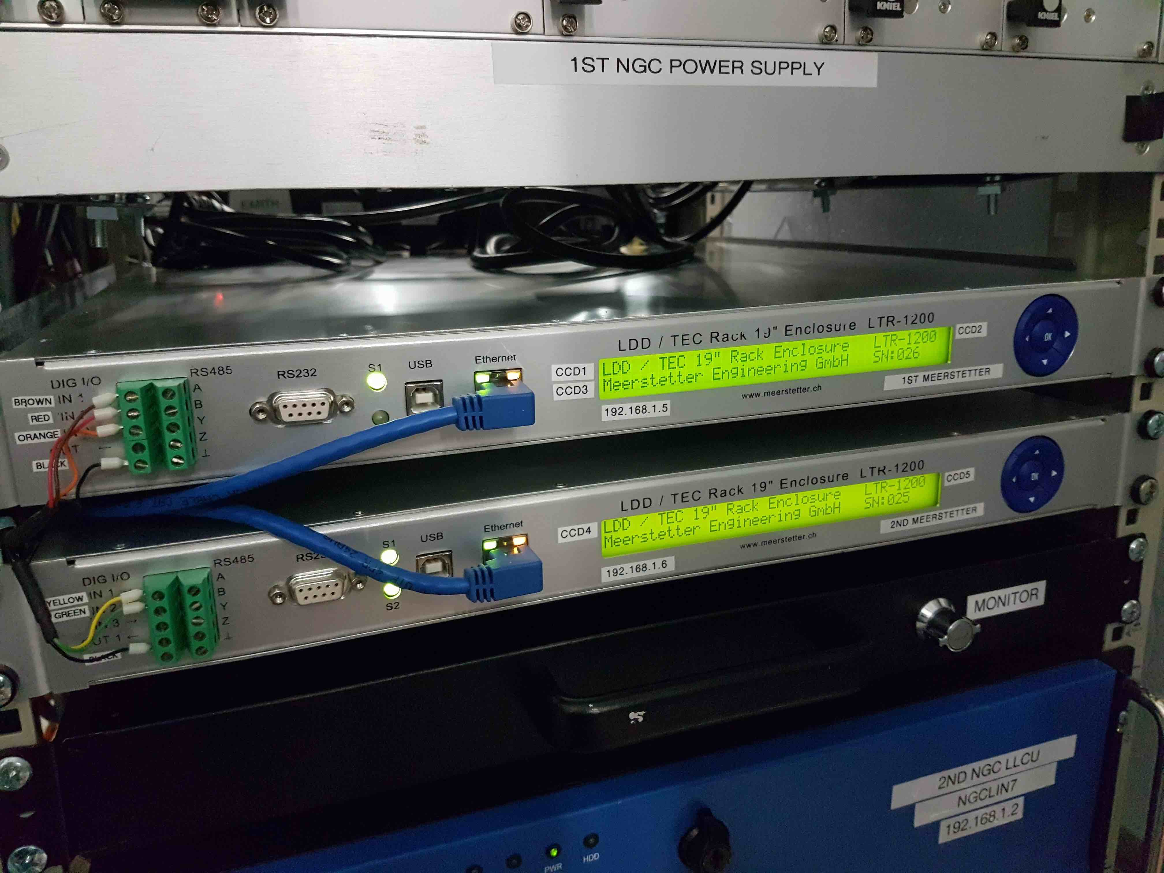
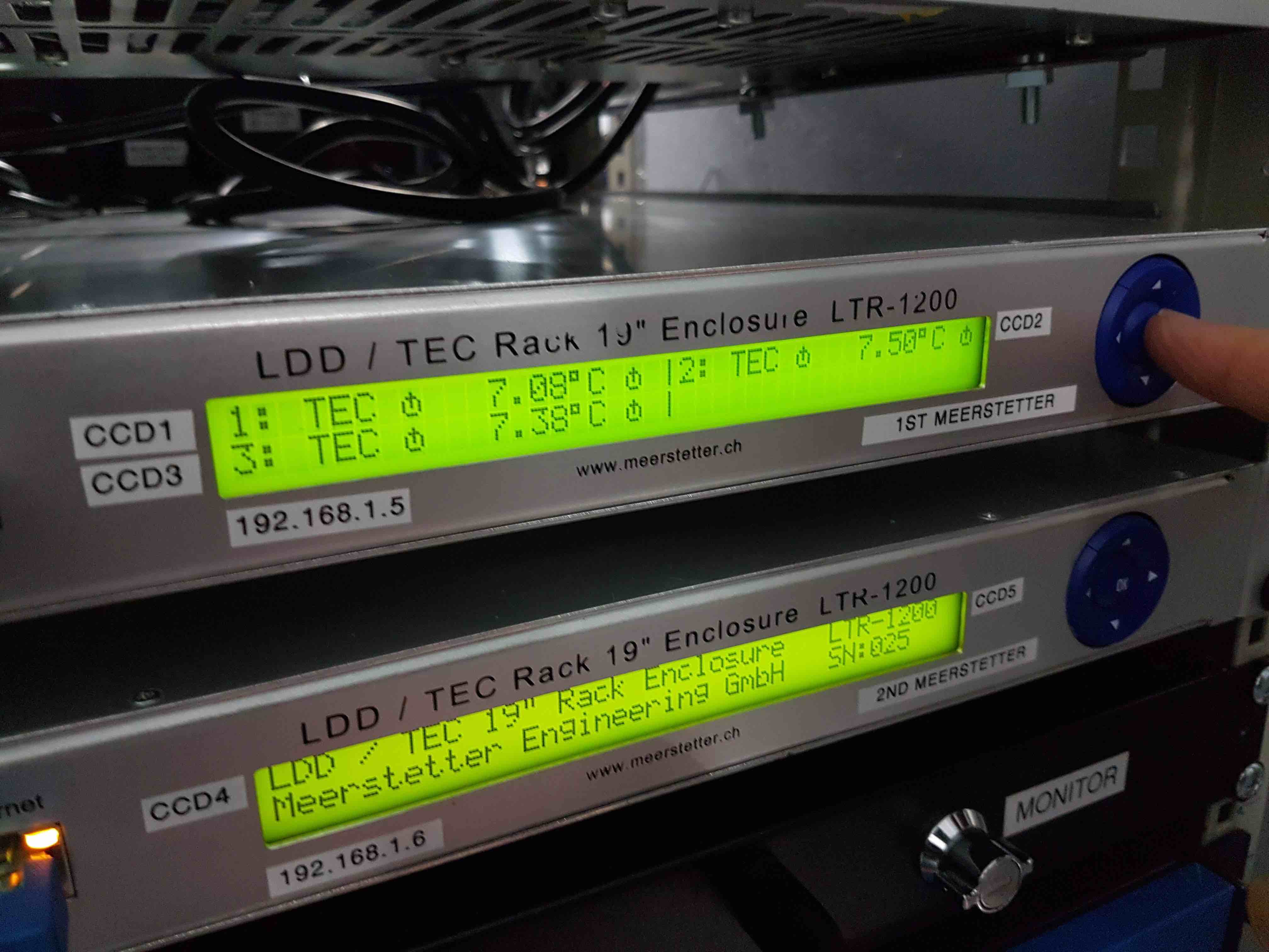
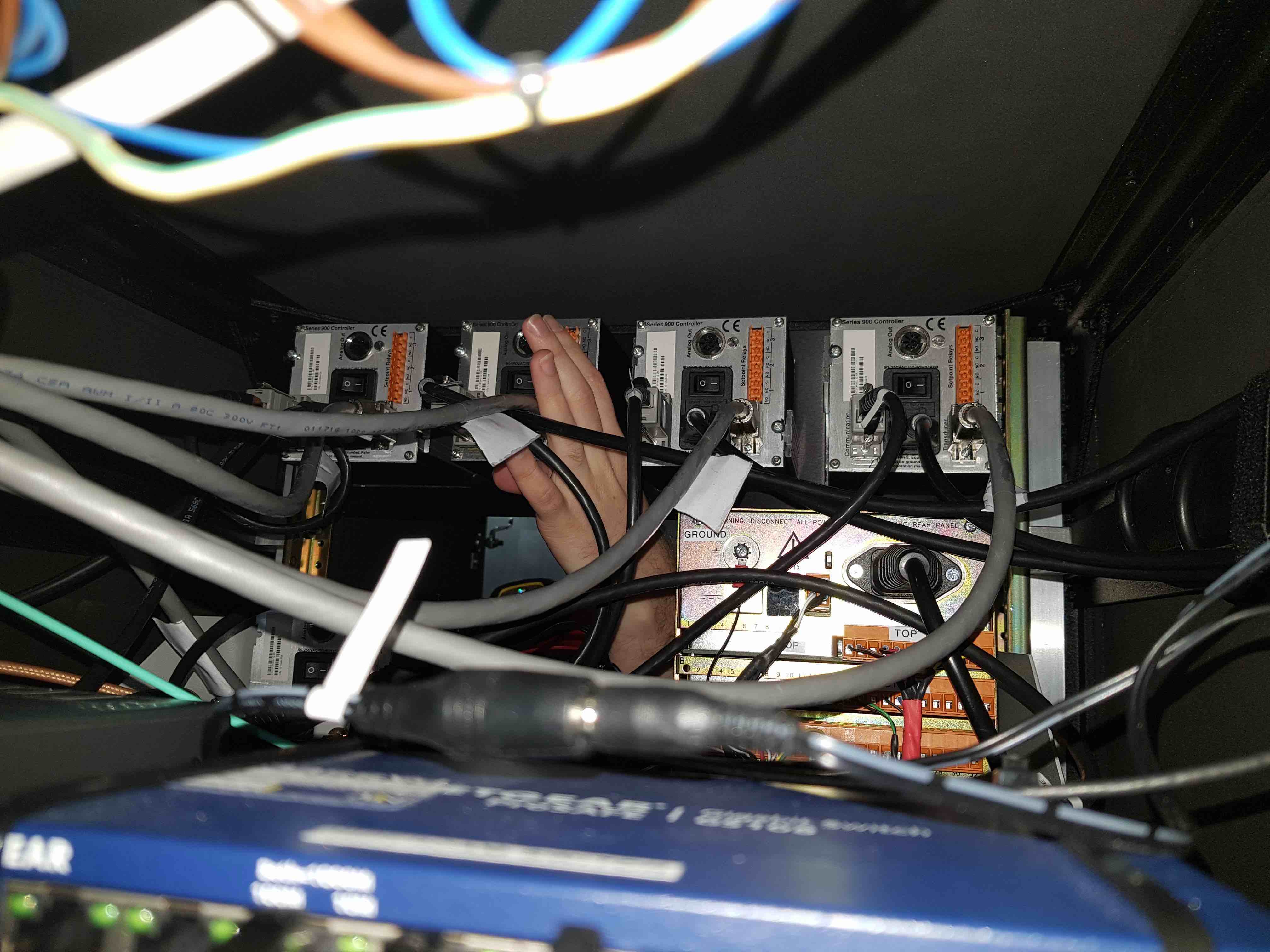
Turn on the two Meerstetter peltier control units by pressing the power switch on the left-hand side of the rear of each unit. The Meerstetters will automatically try to cool/heat the CCDs to whatever value the temperature was last set to. To prevent this from occurring, it is best to ensure that there is no coolant flowing through HiPERCAM prior to turning the Meerstetters on - see pumping and cooling for how to turn the coolant off. To ensure that everything is working correctly, check that the two green LEDs on the front of each Meerstetter unit are flashing and that the CCD and heatsink temperatures are all approximately +10degC. You can find these temperatures by pressing the round blue middle button, which will take you from the LDD/TEC home screen to a display showing all 3 CCD temperatures. Then press the down button three times to see the CCD and heatsink temperatures of all 3 CCDs in turn.
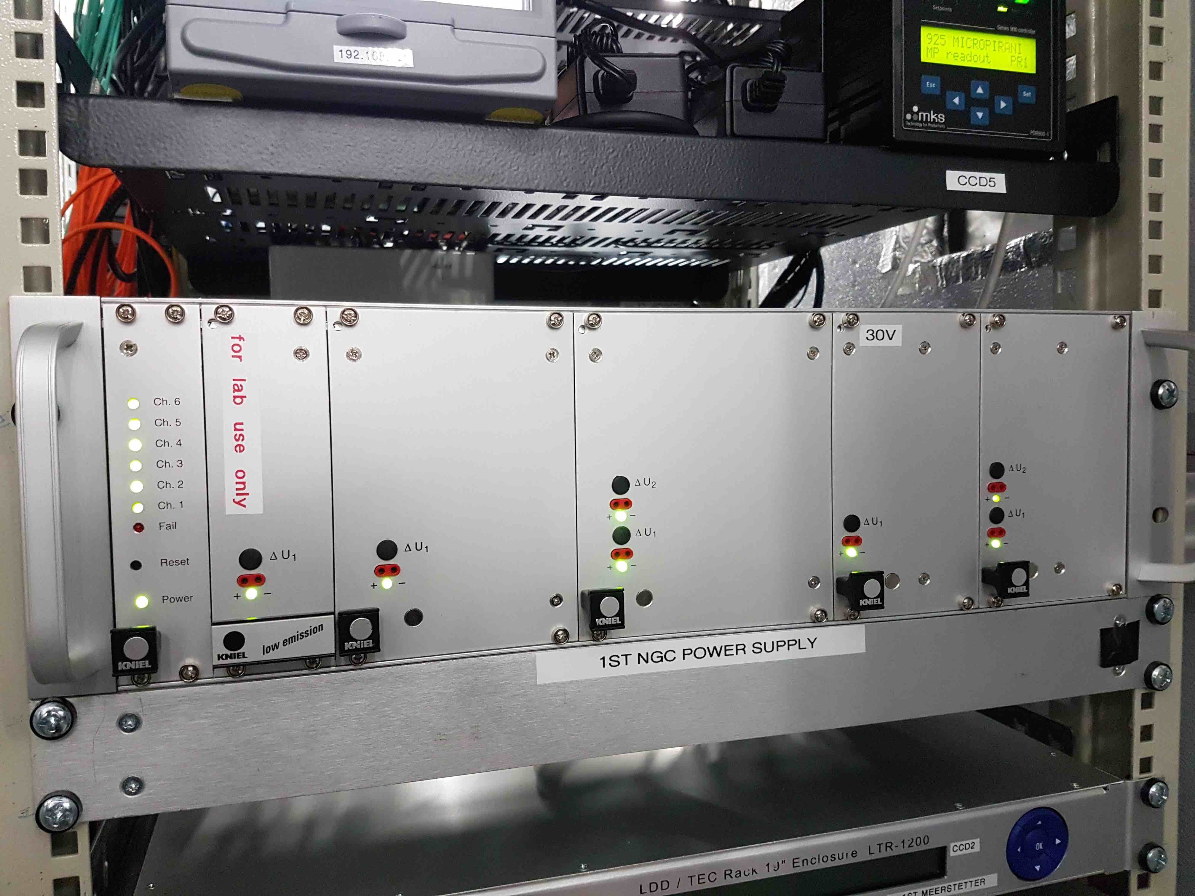
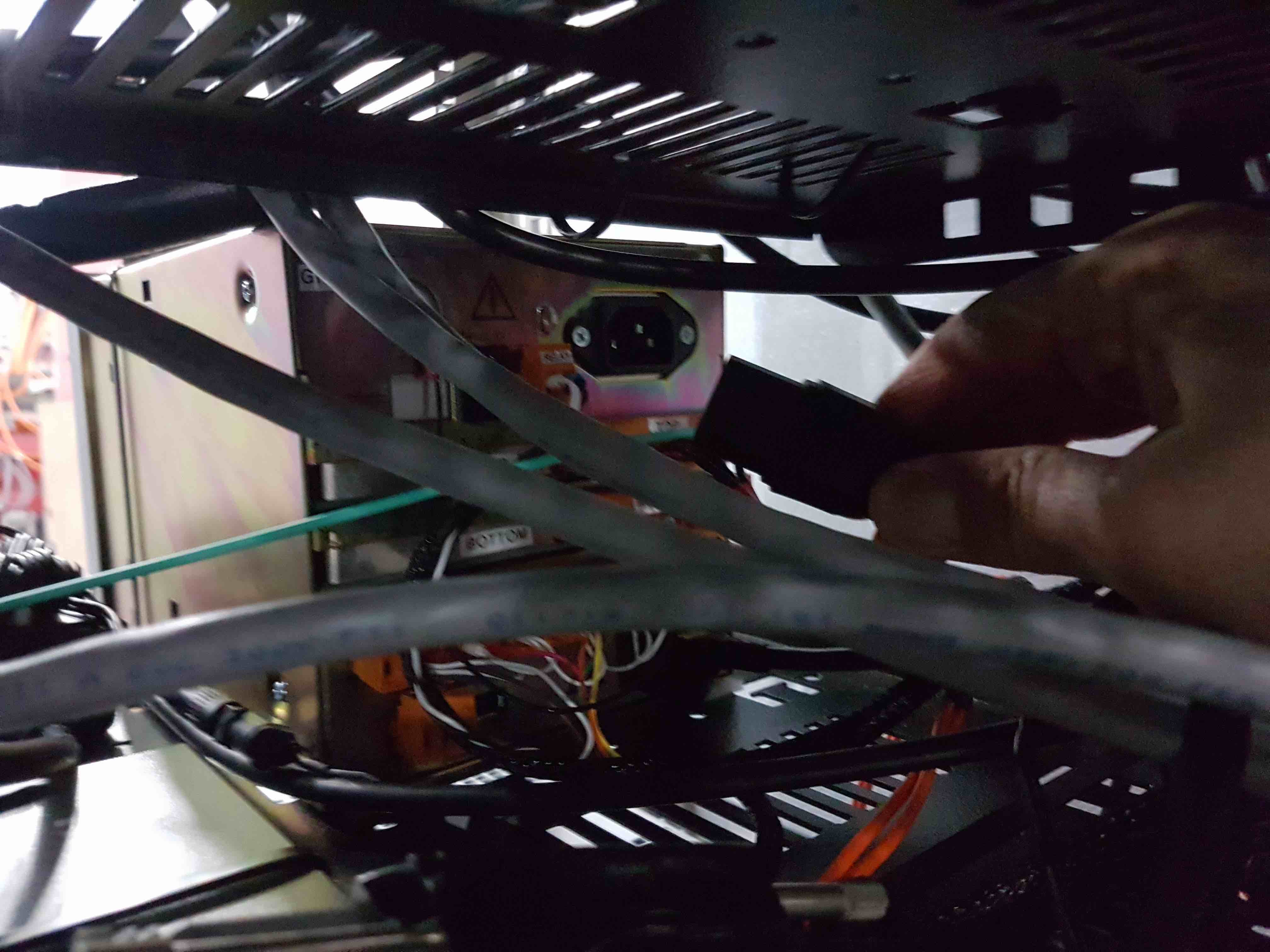
Turn on the NGC PSU by pressing the power switch at the top right-hand side of the rear of the unit. You should see a series of green LEDs illuminate on the front of the unit. Note that the NGC PSU has a tray of fans at its bottom - these are automatically turned on when the cabinet power is switched on. If the fans are not on, check that the IEC connector at the lower-left of the rear of the unit is connected. With the NGC PSU powered on, the red LEDs on the NGC on HiPERCAM should also be illuminated (under the velcro covers). At this point, it would also be worth checking that you can power on the HiPERCAM CCDs by clicking the Power on button in the Setup page of
hdriver, as described in software startup. You may need to try this twice to get it working.
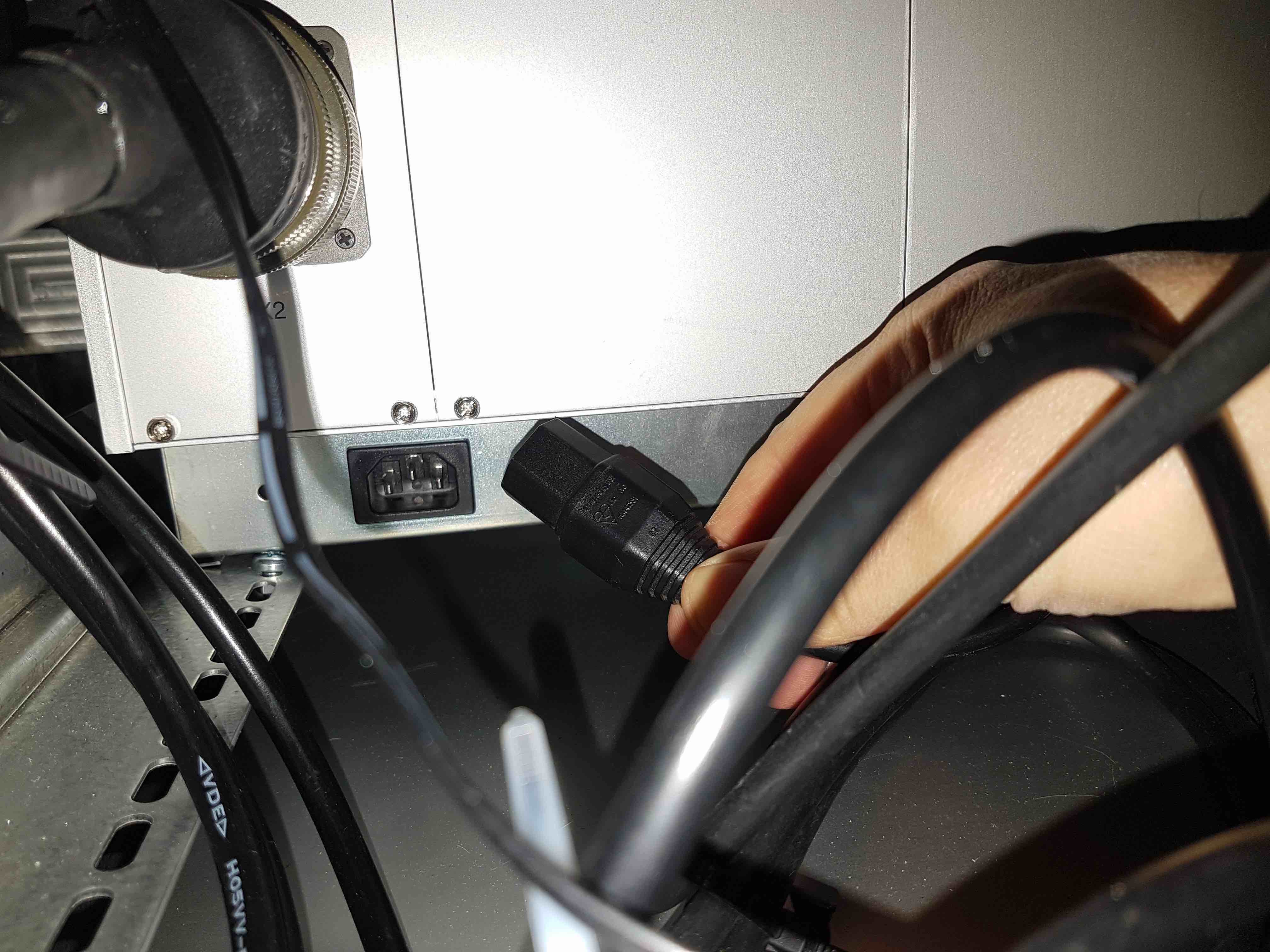
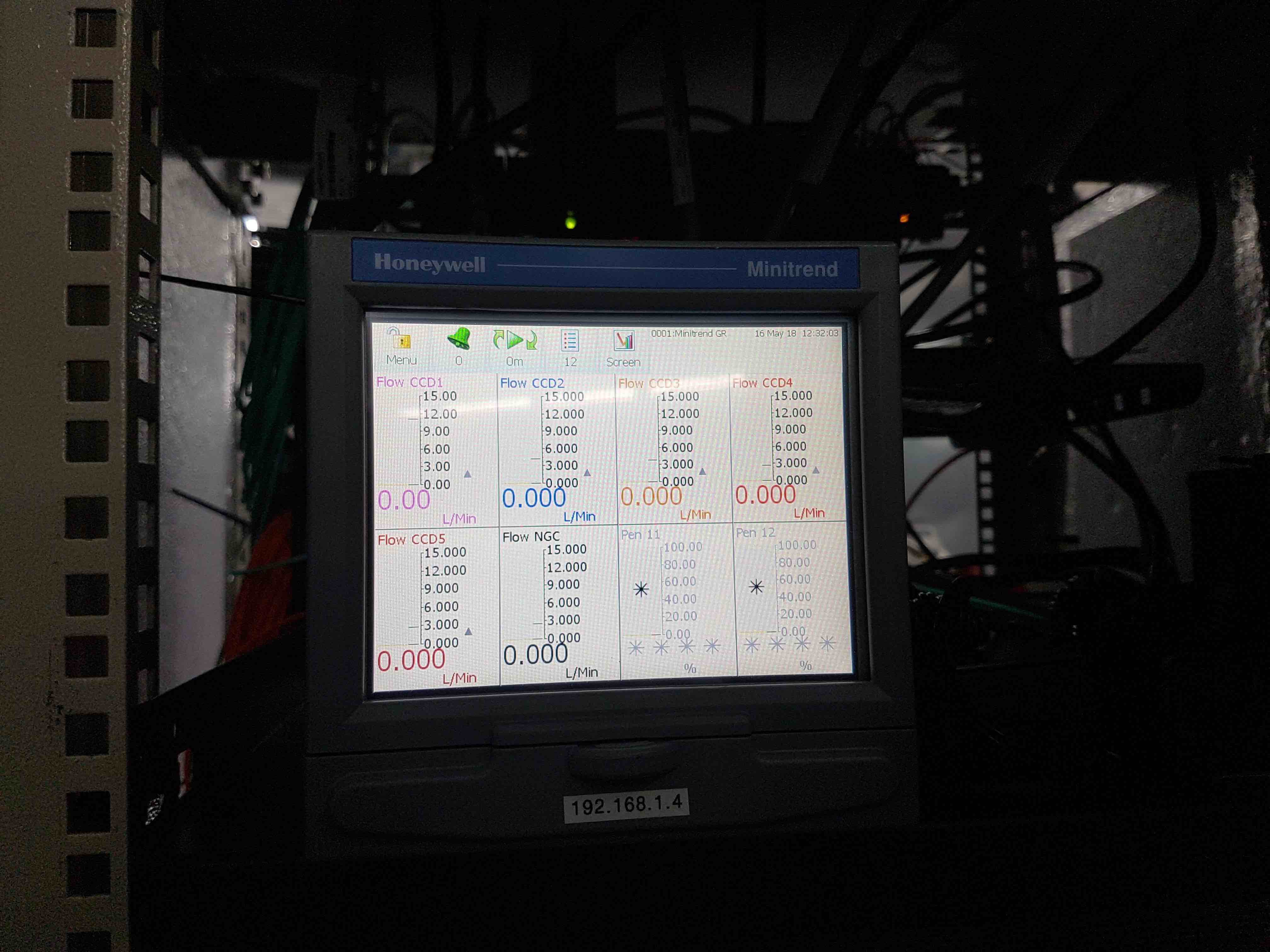
The Honeywell data recorder has no power switch and should come on automatically when the cabinet power is turned on. If it does not, check that the IEC connector on the upper right-hand side of the rear of the unit is connected.
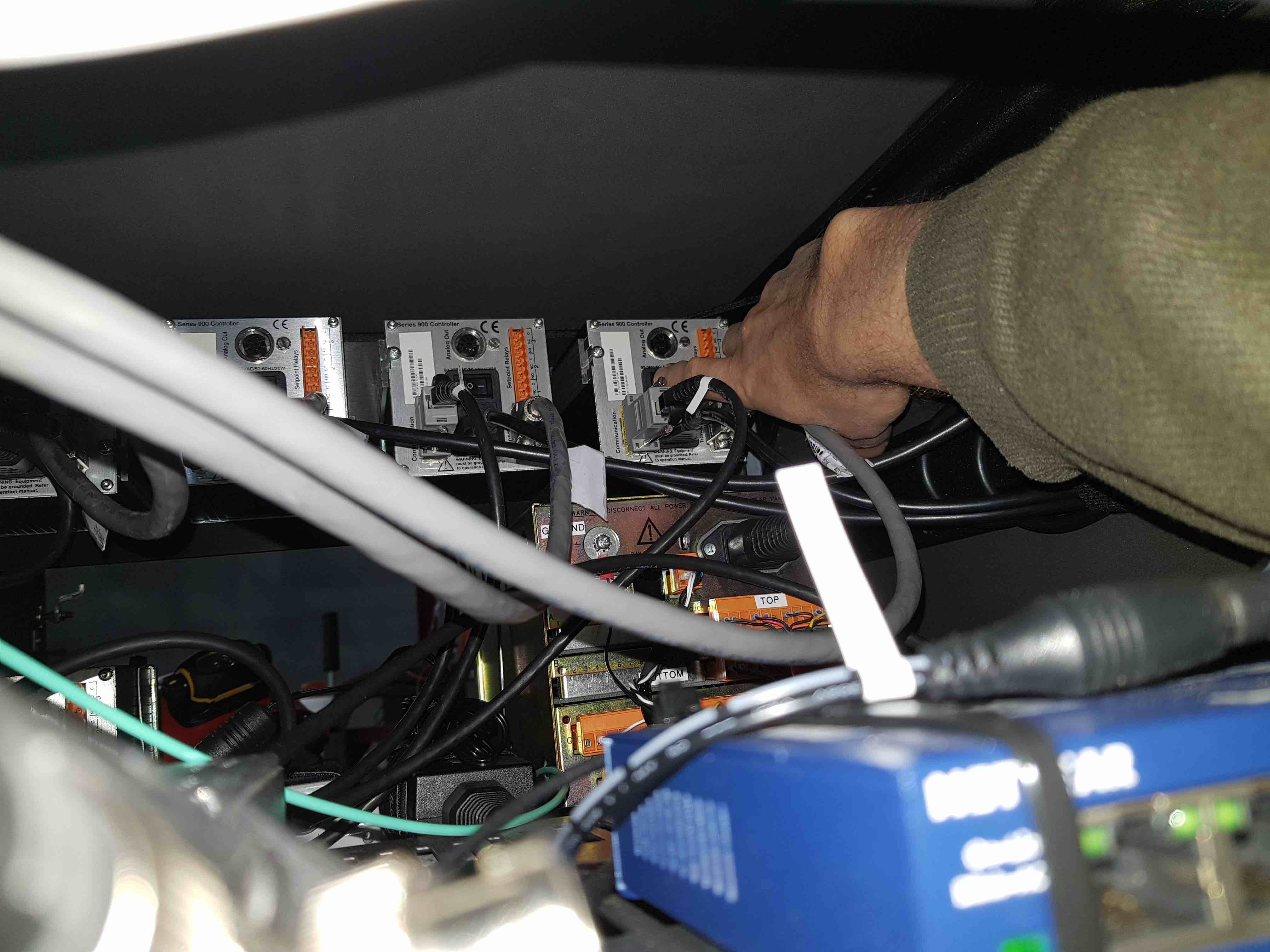
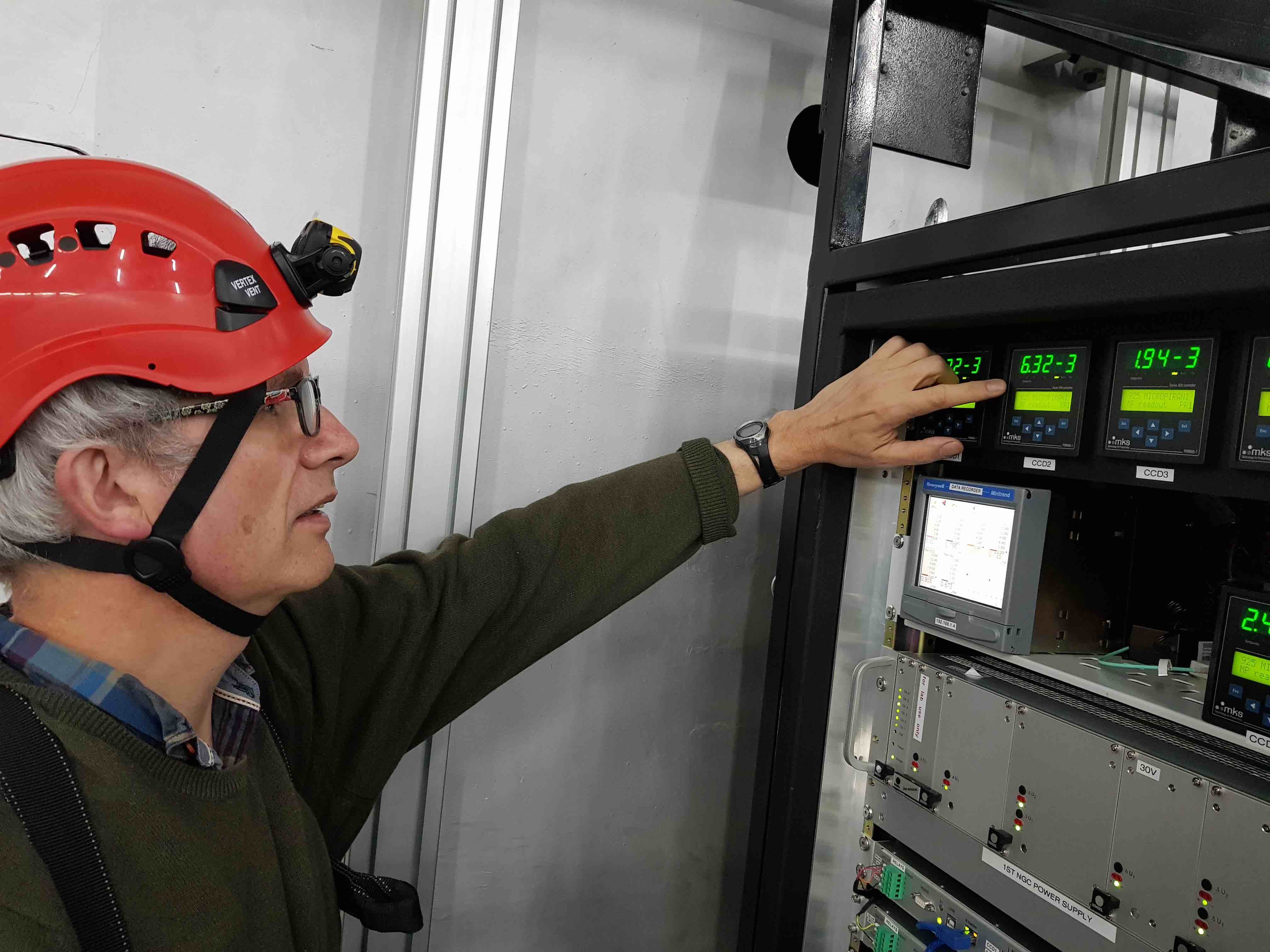
Turn on the vacuum gauge controllers. For CCDs 2 to 5, this can be done most easily by reaching in to the rear of each controller from the front of the cabinet and pressing the power switch. For CCD1, this is most easily done by reaching in from the rear of the cabinet.
With all of the hardware powered up, you must now be careful when closing the cabinet doors, as the heat being generated could raise the inner temperature to dangerous levels. Before closing the doors, make sure that the cabinet cooler is running and that the cabinet temperature is being automatically monitored by the GTC.
The next step is to begin pumping and cooling the CCDs.