Pumping and cooling down
This section describes how to pump and cool down HiPERCAM’s CCDs.
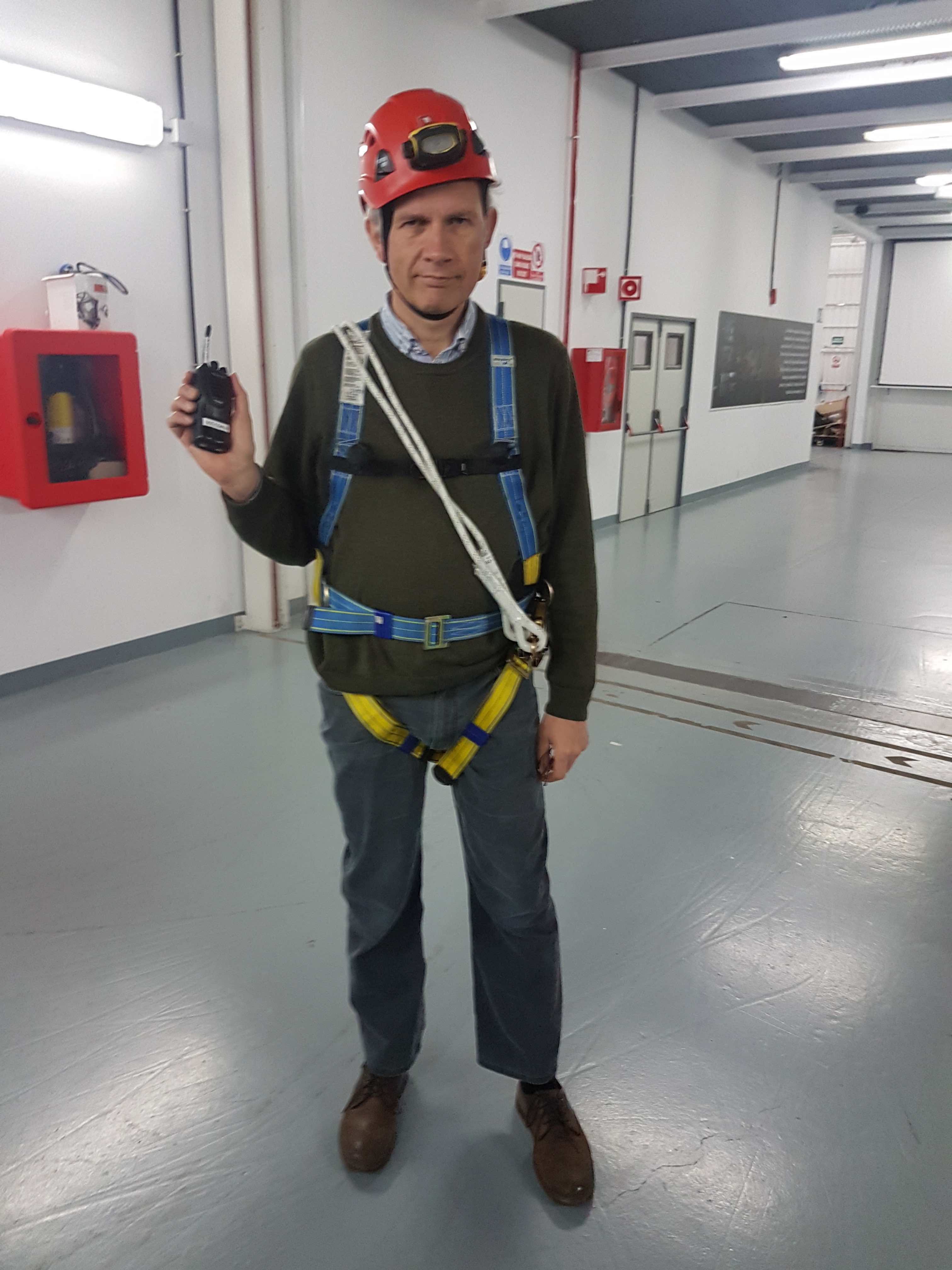
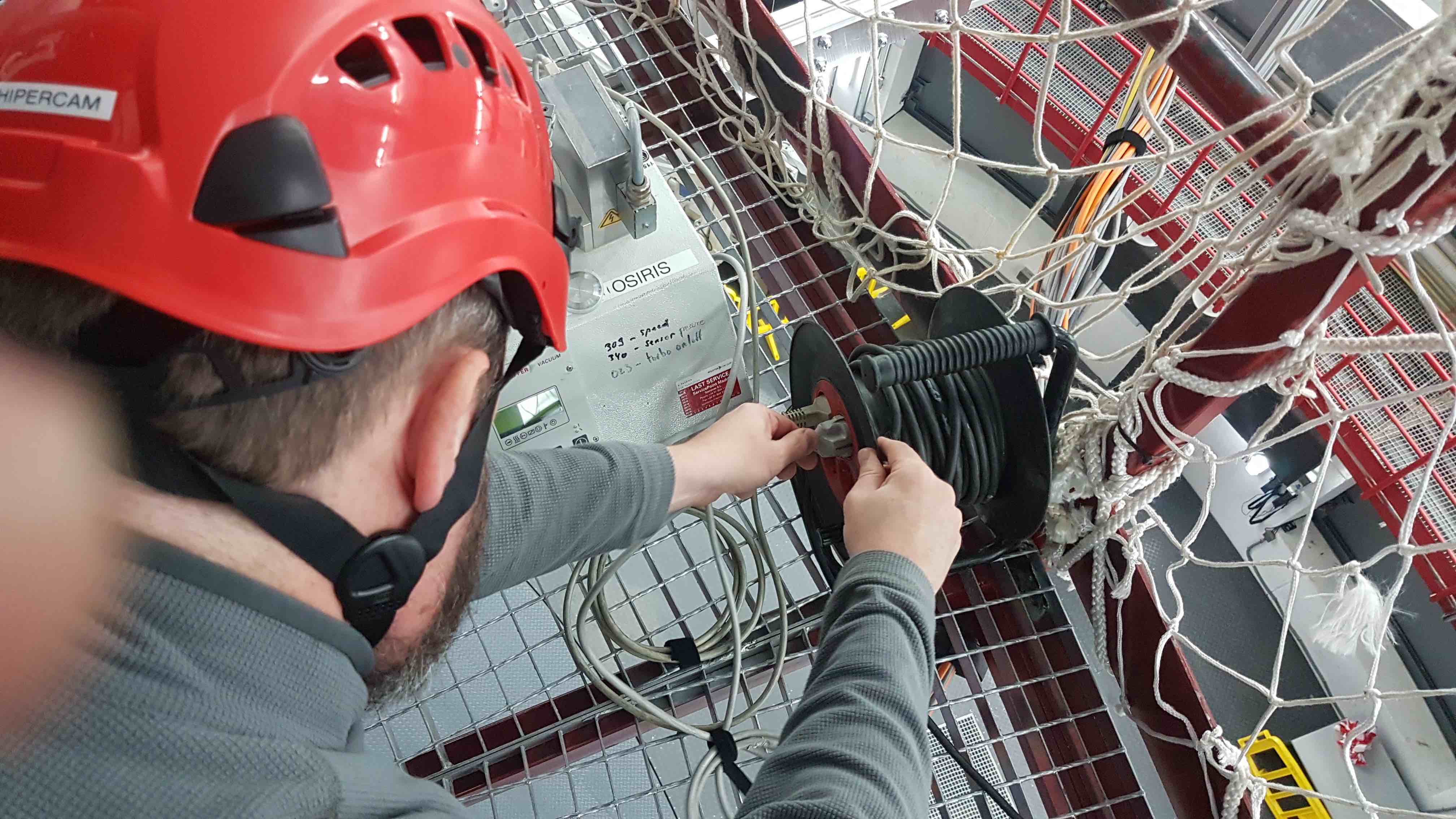
You will need to access the Elevation (Folded Cassegrain) Platform in order to pump and cool HiPERCAM. Only HiPERCAM team members who have completed the relevant safety courses and GTC paperwork, and have GTC permission to do so, are allowed to access this area. Before going up to the platform, put on your personal protection equipment, including: helmet with chin strap, safety shoes/boots, safety harness with lanyard and scaffold hooks (located in the HiPERCAM crates), and safety gloves (if necessary). Make sure that you have a radio, set to channel 8, and that you have told the GTC Jefe de Turno (during the day) or Telescope Operator (during the night) if it is ok for you to go up to the platform. He or she will have to slew the telescope to vertical, insert the elevation axis locking pins and turn on the dome lights.
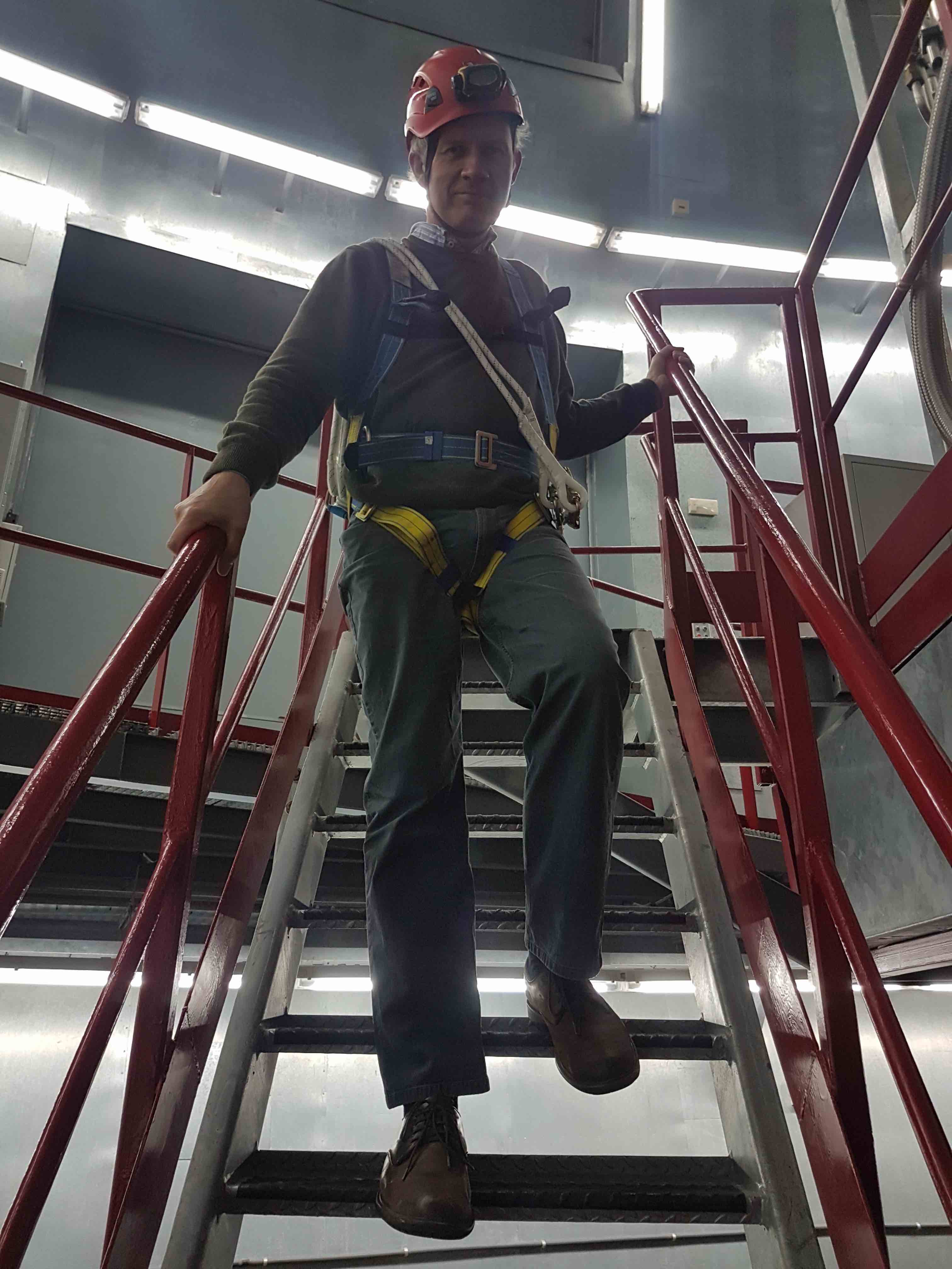
On your way up to the platform, do not carry anything in your hands that would prevent you from safely using the stair rails on your way up - any such equipment should be transported to the platform using the cradle and crane. When descending the platform, always place one hand on the stair rail behind you and one on the rail in front of you, as shown in the photo below.
Note: The policy on wearing safety harnesses when accessing the elevation platform at the GTC is in a state of flux - it is possible that it may be relaxed in the future due to the existence of the railing around the elevation platform. For up to date information on this, please ask the Jefe de Turno or Telescope Operator prior to accessing the platform.
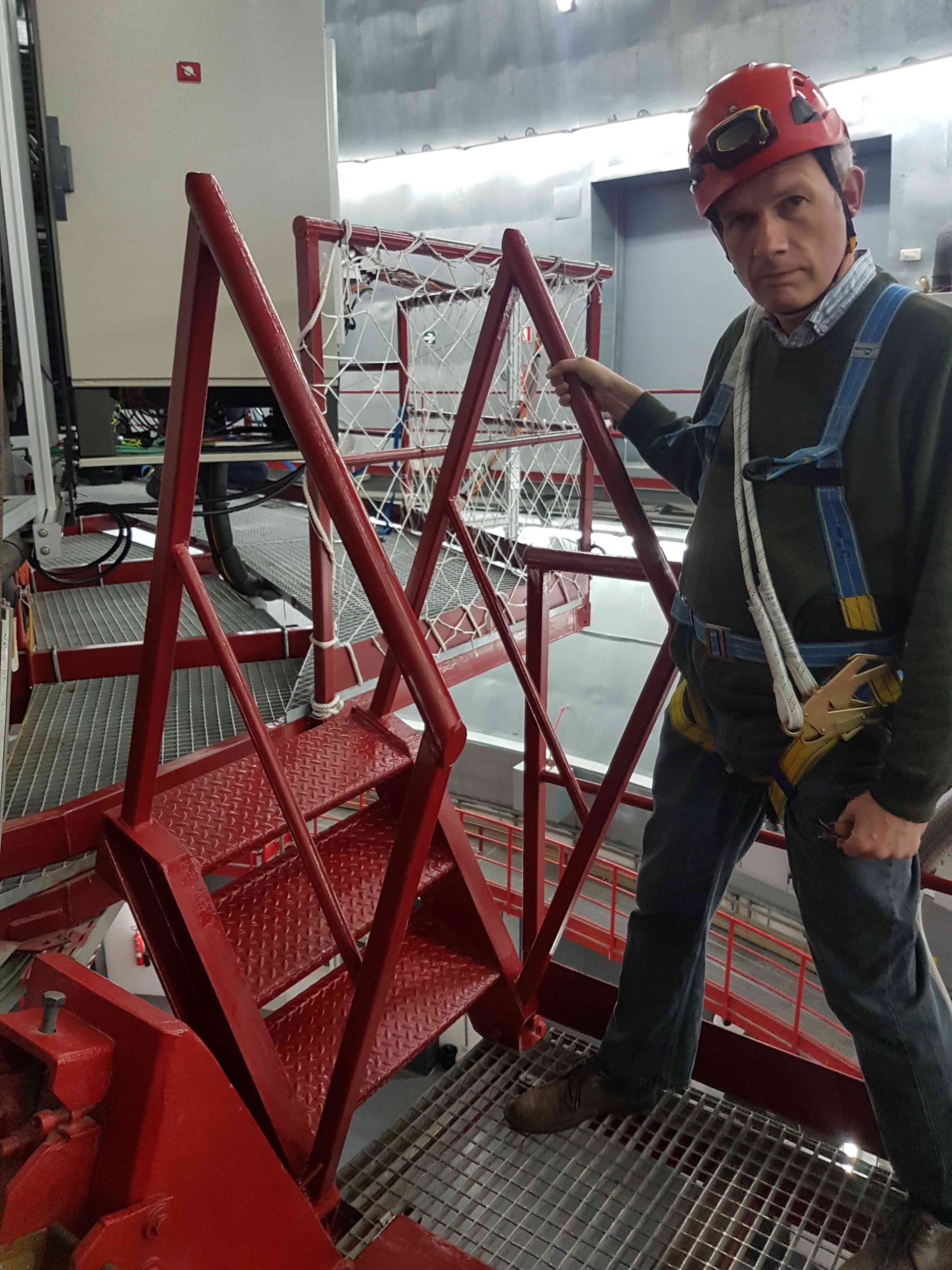
- Once on the platform, carefully pivot the access stairs if they are not already down. It has been known for the telescope elevation to be incorrectly positioned, forcing the access stairs to rest on a flimsy piece of metal conduit rather than the red railing. In this case, ask the Jefe de Turno or Telescope Operator to adjust the telescope elevation accordingly.
The next step is to vacuum pump the CCD heads. The principle here is that cooling the CCDs when the heads do not contain a good vacuum risks condensation forming on the detectors. So you must only ever cool down the CCDs whilst pumping.
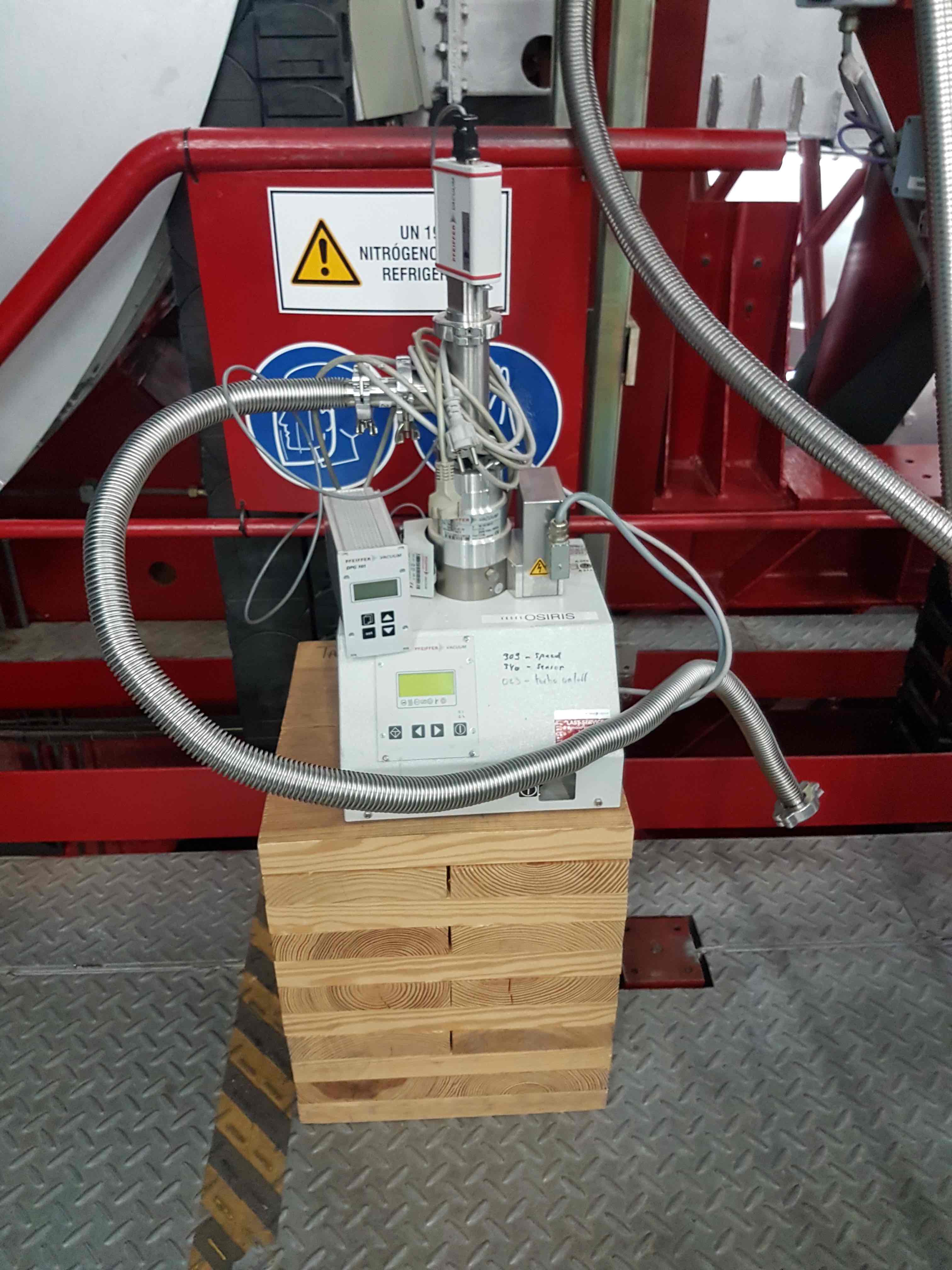
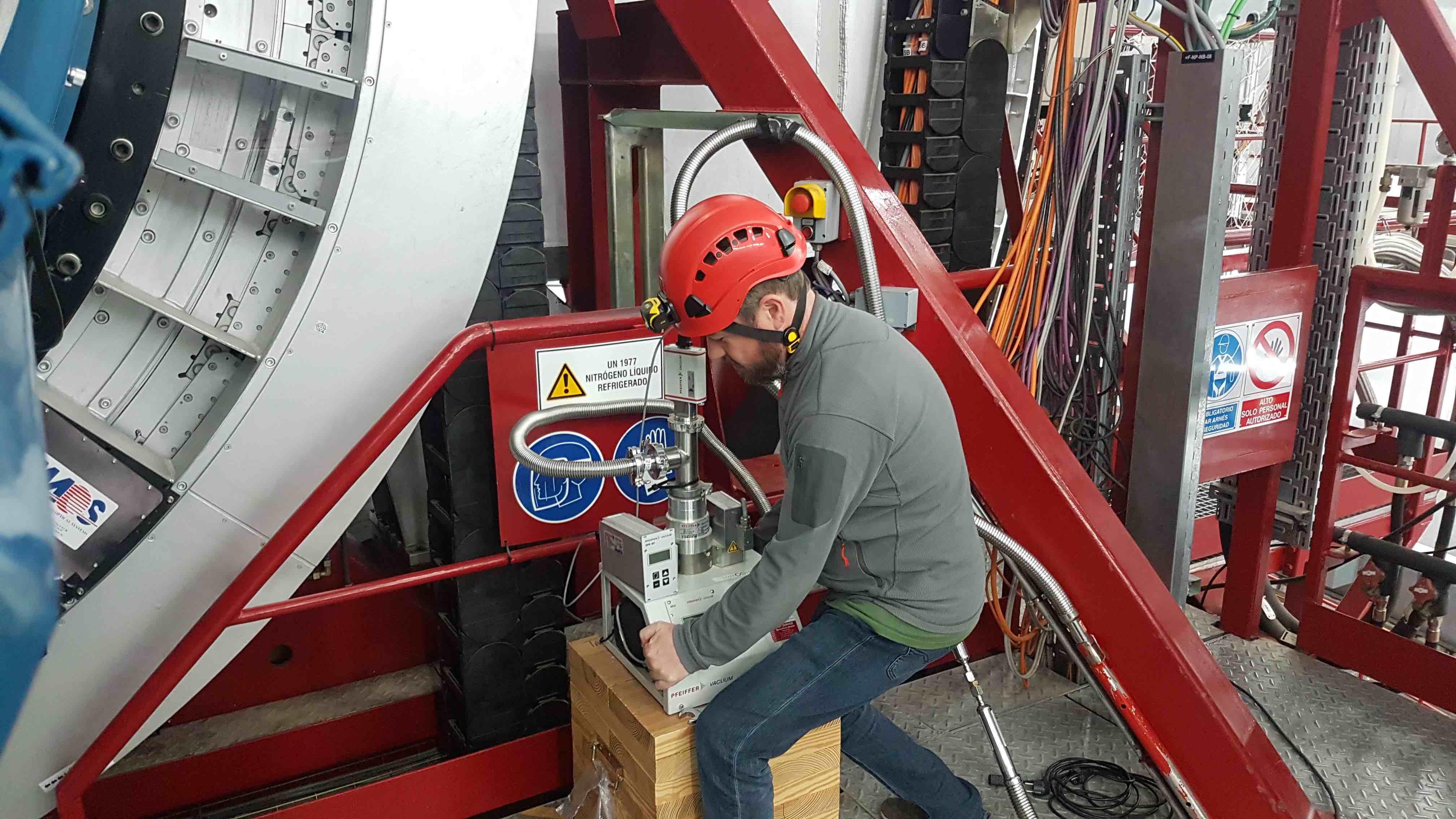
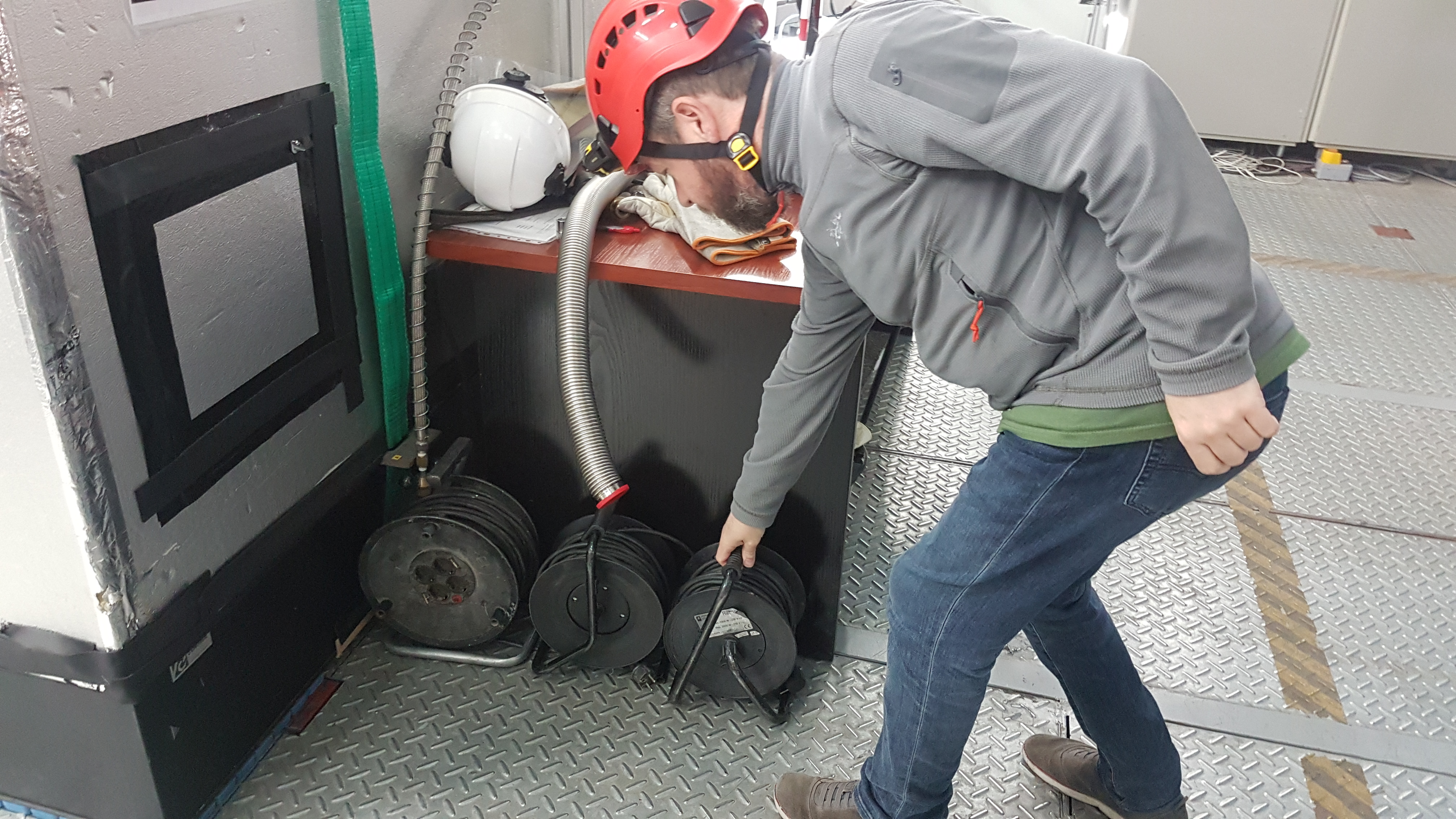
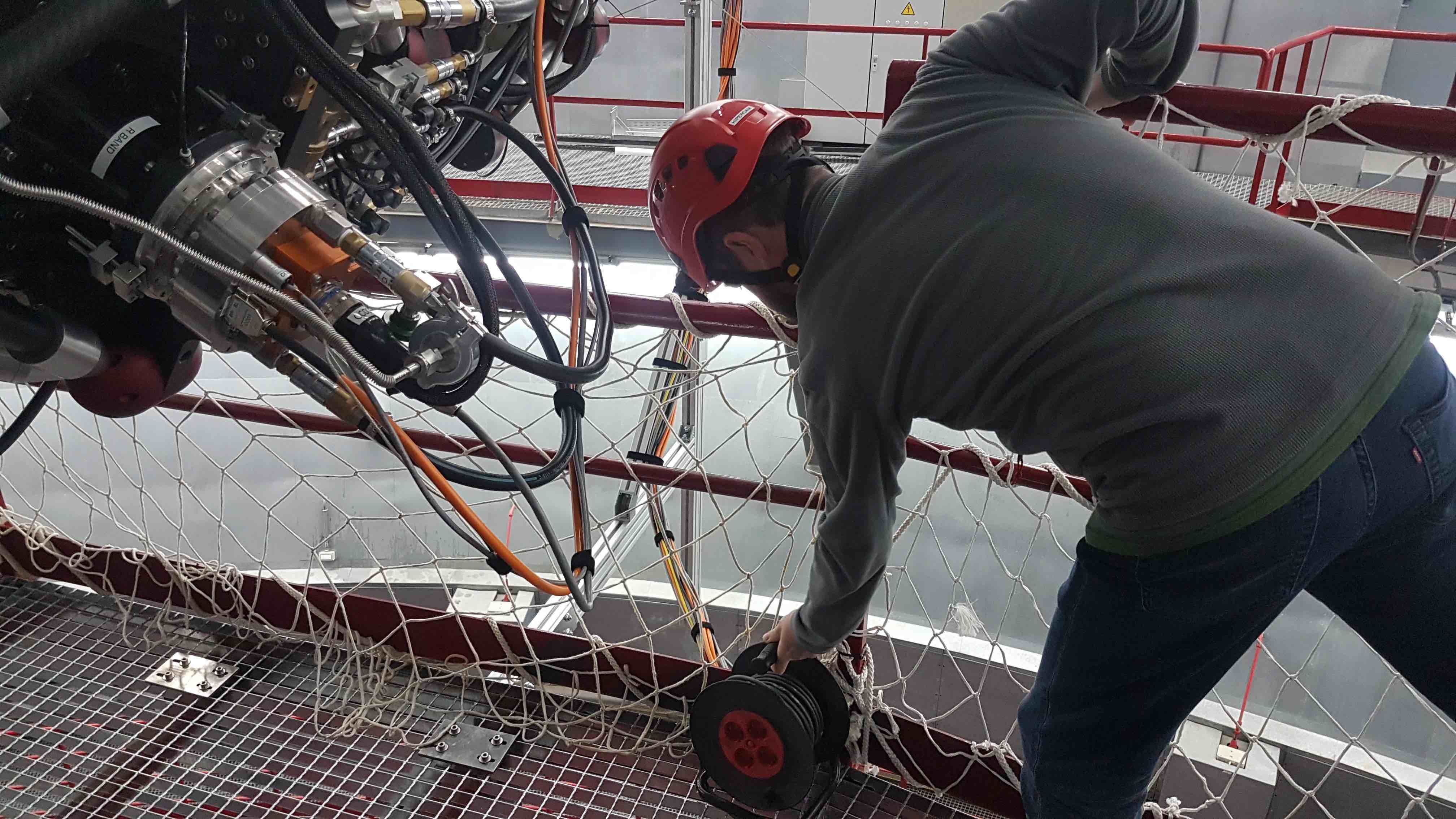
We use the OSIRIS vacuum pump, which is stored on top of a wooden box on the OSIRIS Nasmyth platform. You will need to carry this to the platform and position it underneath HiPERCAM. You will also need to run a mains extension reel from the UPS power point above the gate to the elevation platform to underneath HiPERCAM.
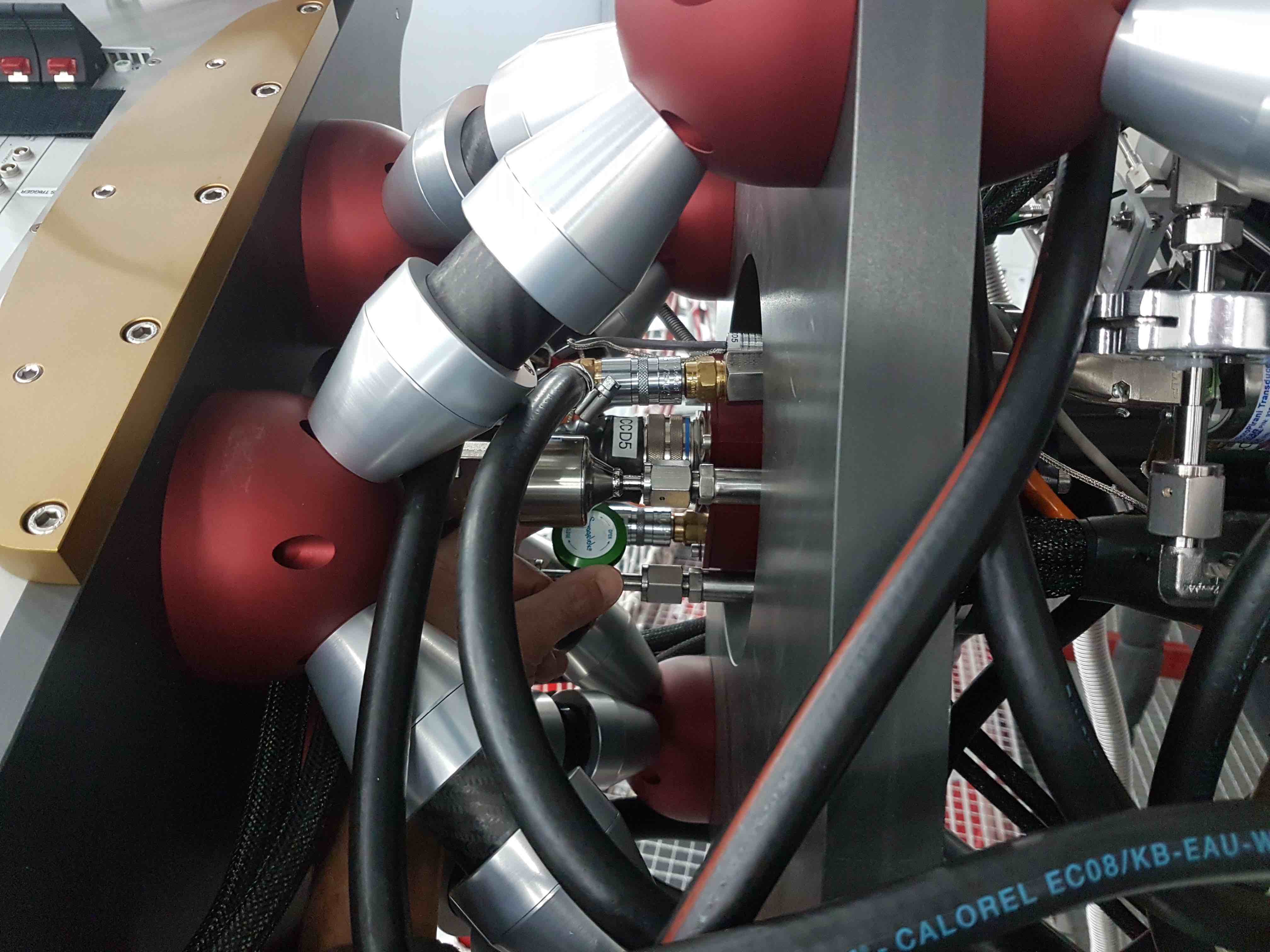
- The vacuum manifold port should be positioned so that it is facing the electronics cabinet. If it is not, rotate the rotator until HiPERCAM is at the correct orientation. If you can’t move the rotator, the brake might be on, in which case you will need to ask the Jefe de Turno or Telescope Operator to release it.
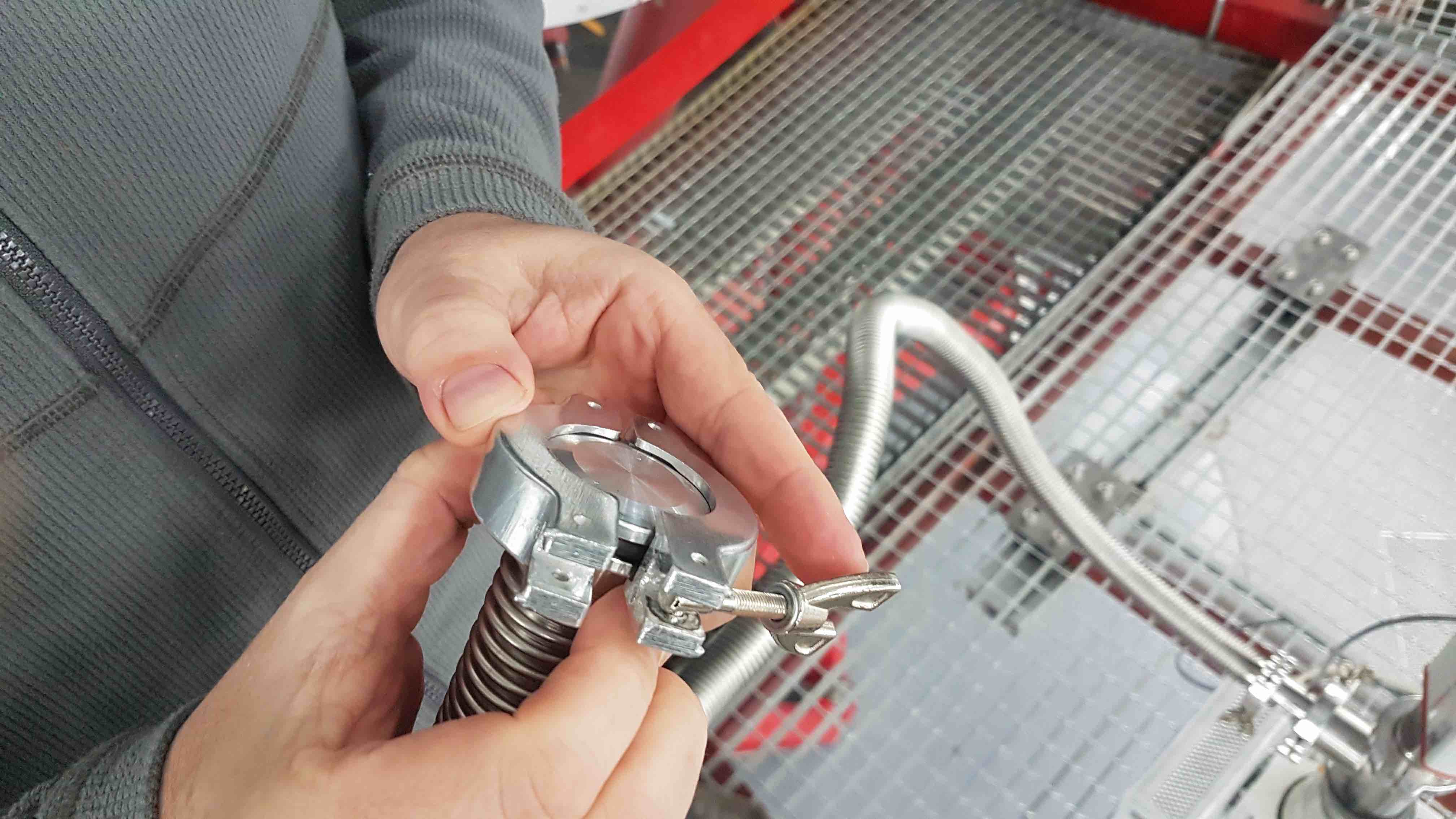
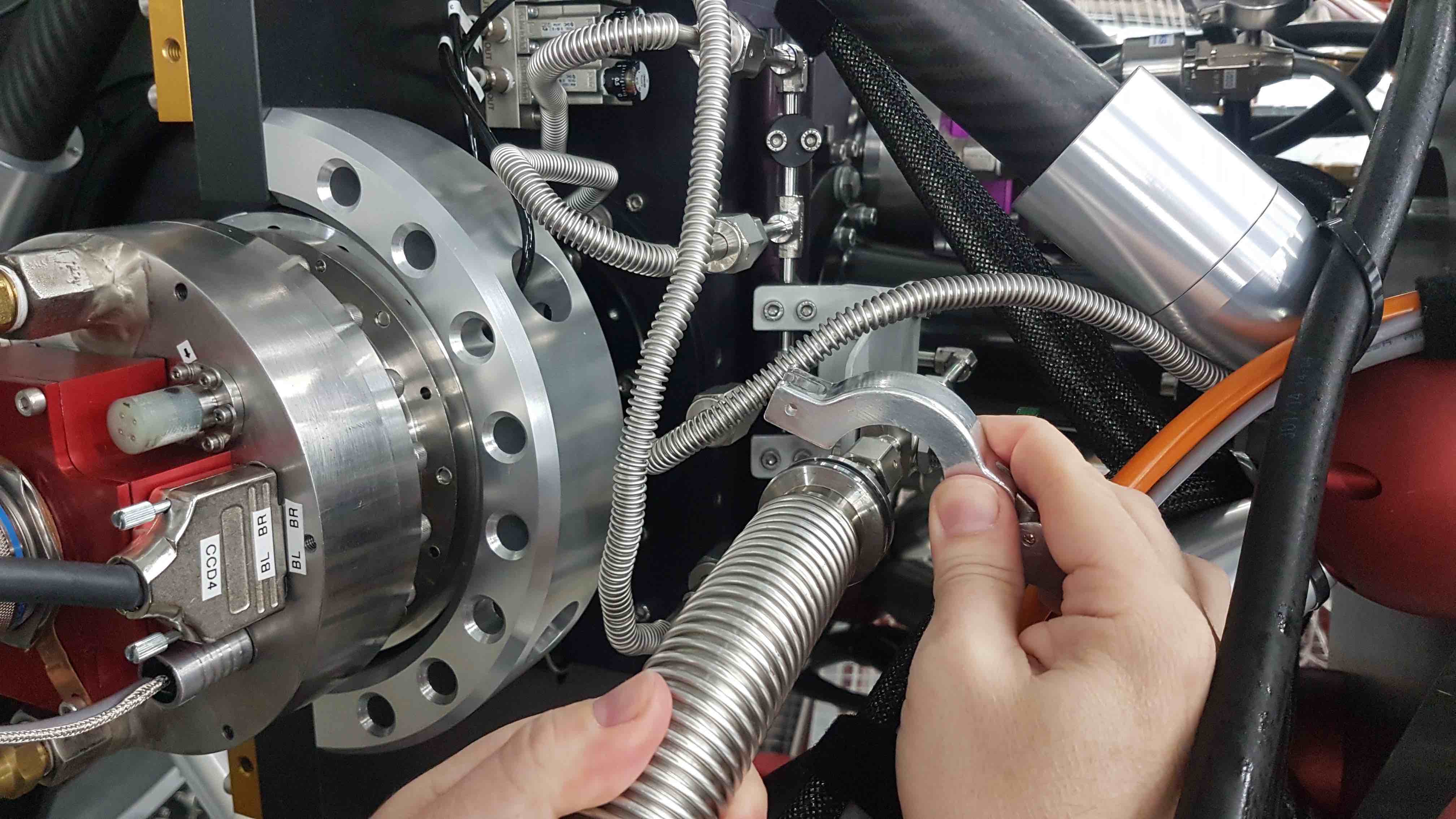
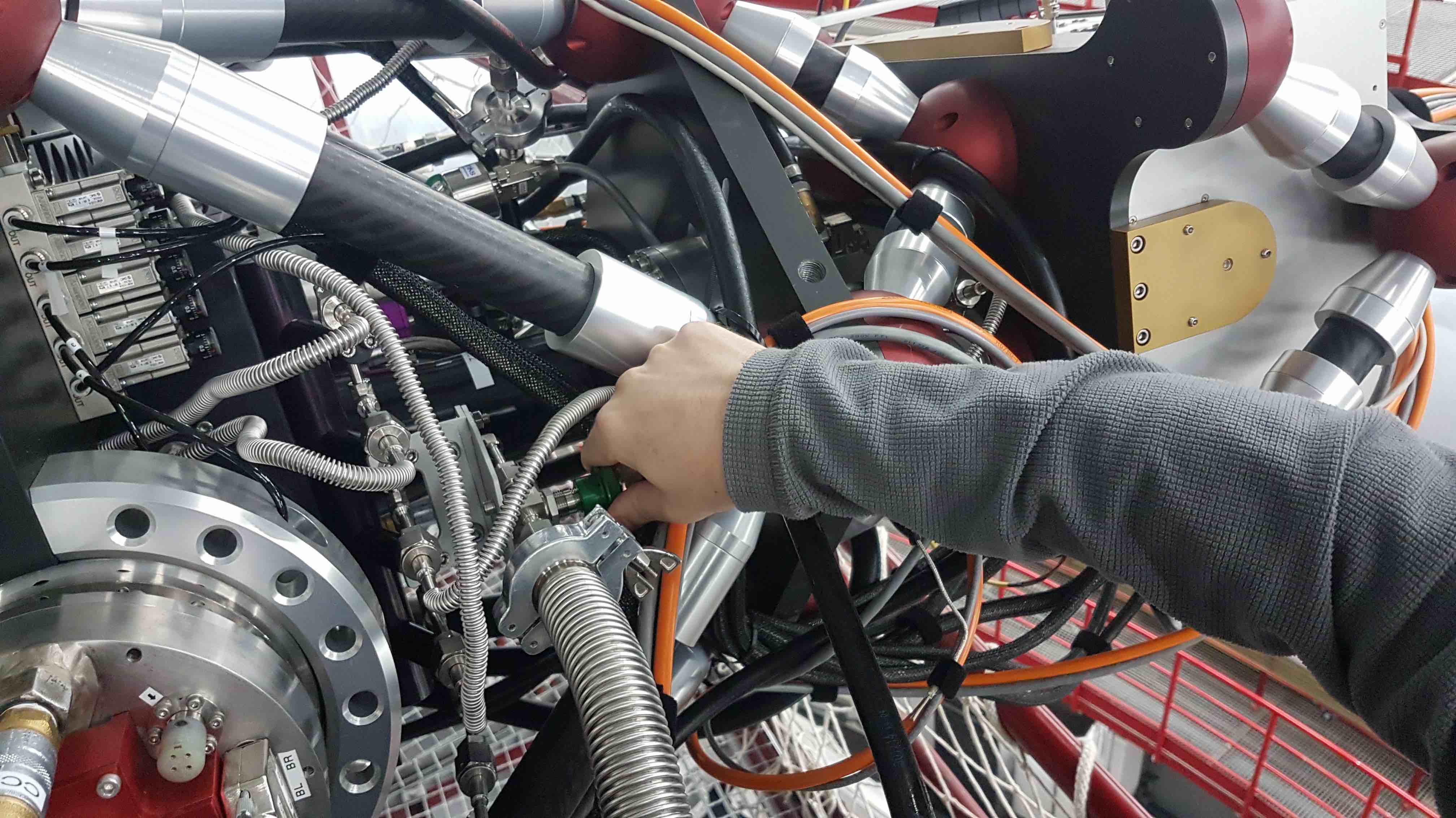
- This pumping procedure assumes that the vacuum manifold is already under a reasonable vacuum. If it is not, refer to item 10 below. First, connect the OSIRIS vacuum pump to the HiPERCAM vacuum manifold. Ensure that the vacuum connection to the manifold is not under any stress by careful positioning of the vacuum hose and pump.
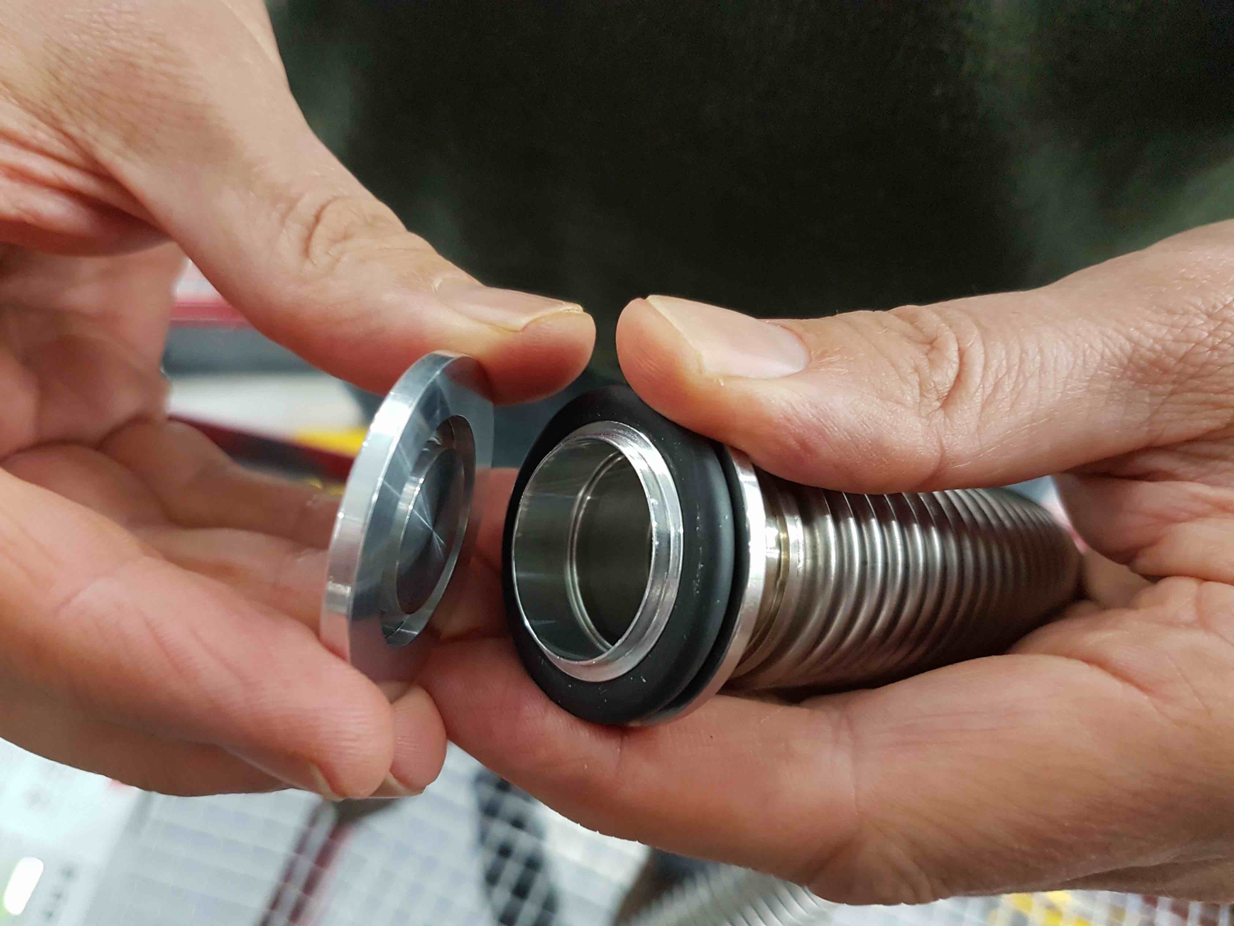
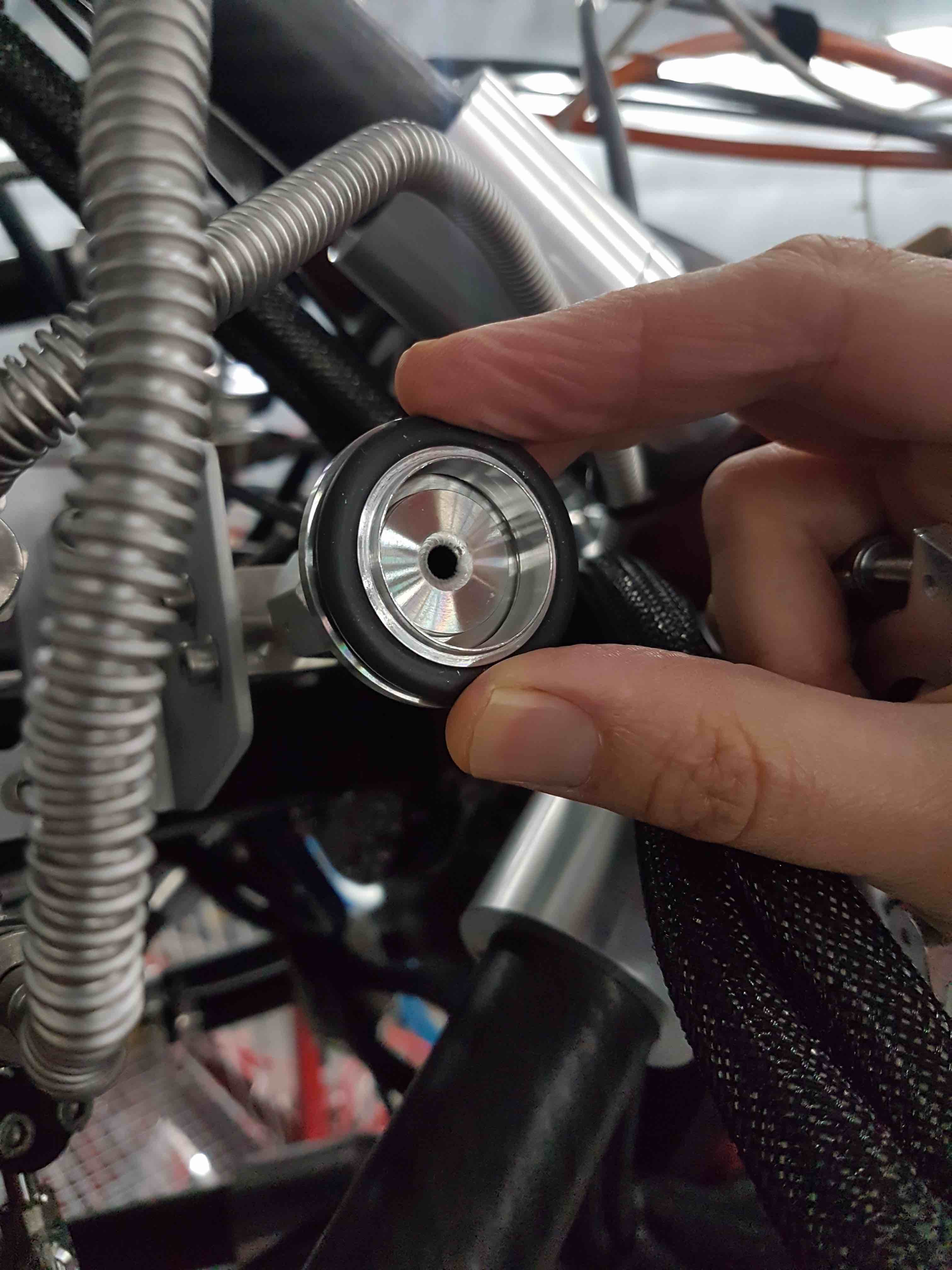
- Keep the mating surfaces, vacuum o-ring, blanking plug and plastic cap clean, and try to avoid touching the inner surfaces. Be careful not to scratch the mating surfaces. The fittings used are called KF fittings and you should try to avoid overtightening the clamps.
- Connect the two power cables from the pump to the mains extension reel lying underneath HiPERCAM. You may need to twist the plugs as you insert them into the sockets. If the pump and gauge displays do not come on, press the toggle switches hidden in the hole on the front panel of the pump and at the rear of the pump vacuum gauge controller (in the separate box). If the backing pump does not come on, press the toggle switch hidden inside the pump on the backing-pump housing.
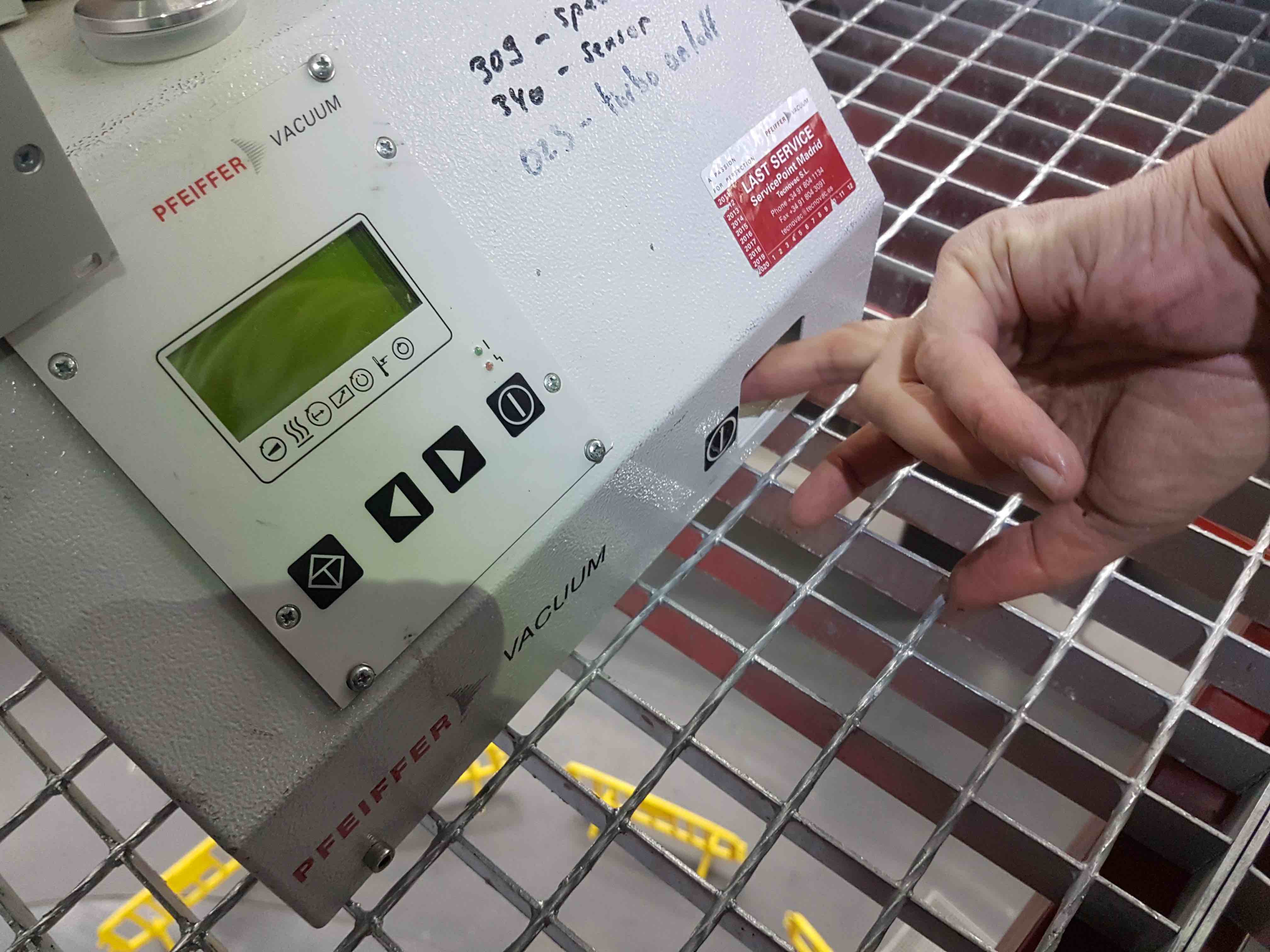
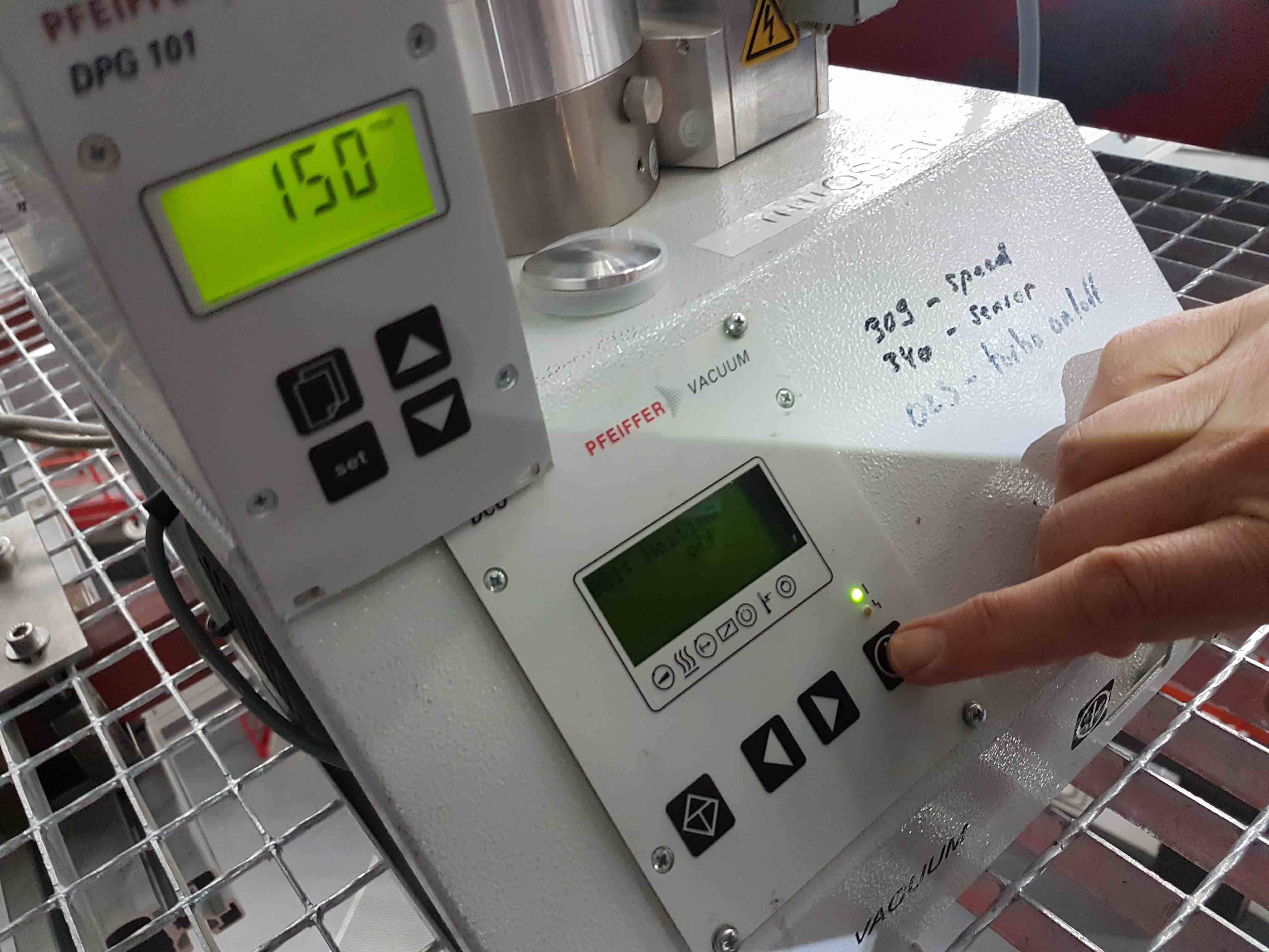
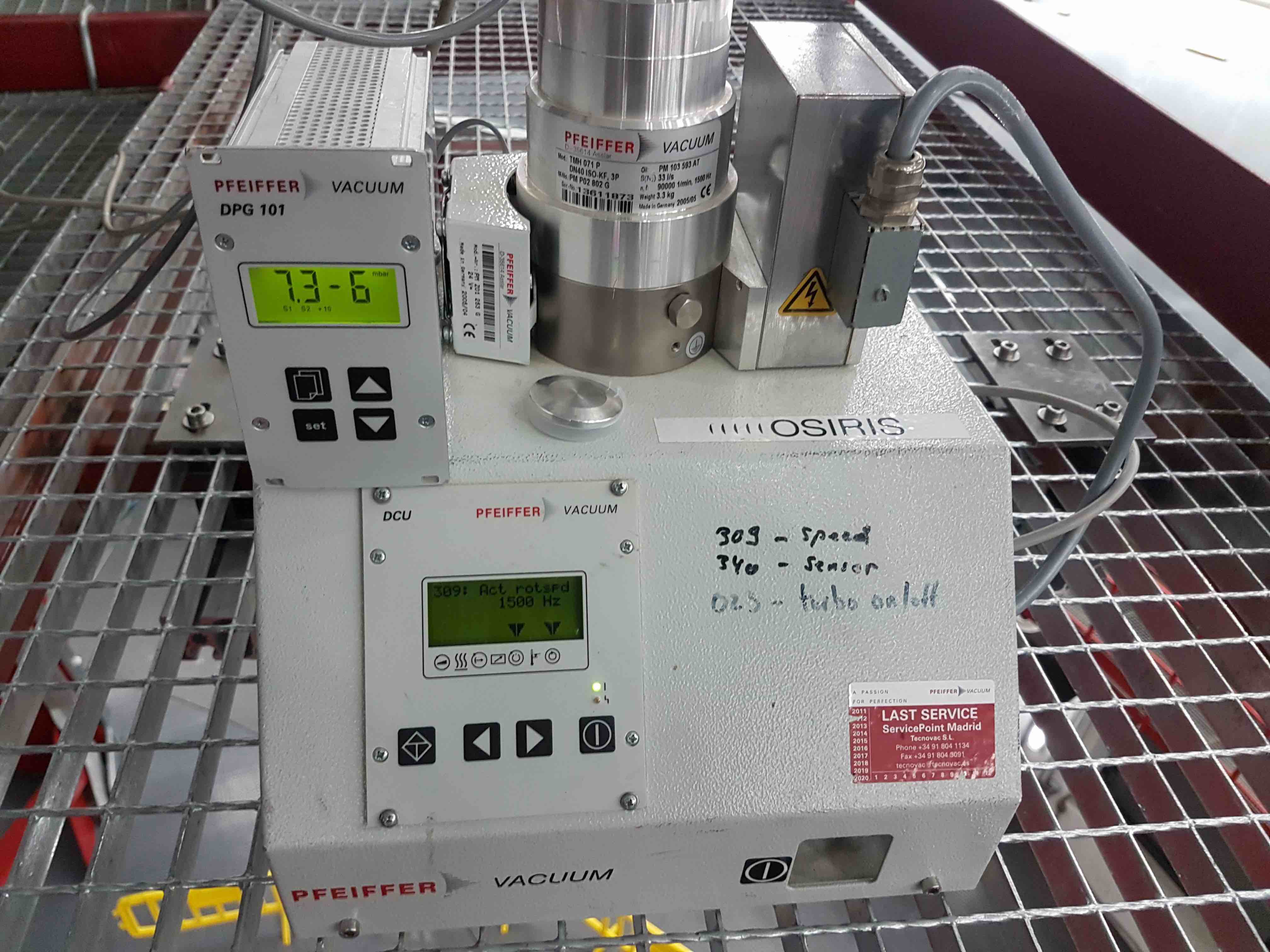
- Ensure that the vent valve at the back of the turbo pump is screwed shut, and then turn on the backing pump and turbo by pressing the black power button on the right-hand side of the front control panel of the pump. You should now hear the turbo speed up. Navigate to the turbo pump frequency display (menu item 309) using the cursor keys on the front panel.
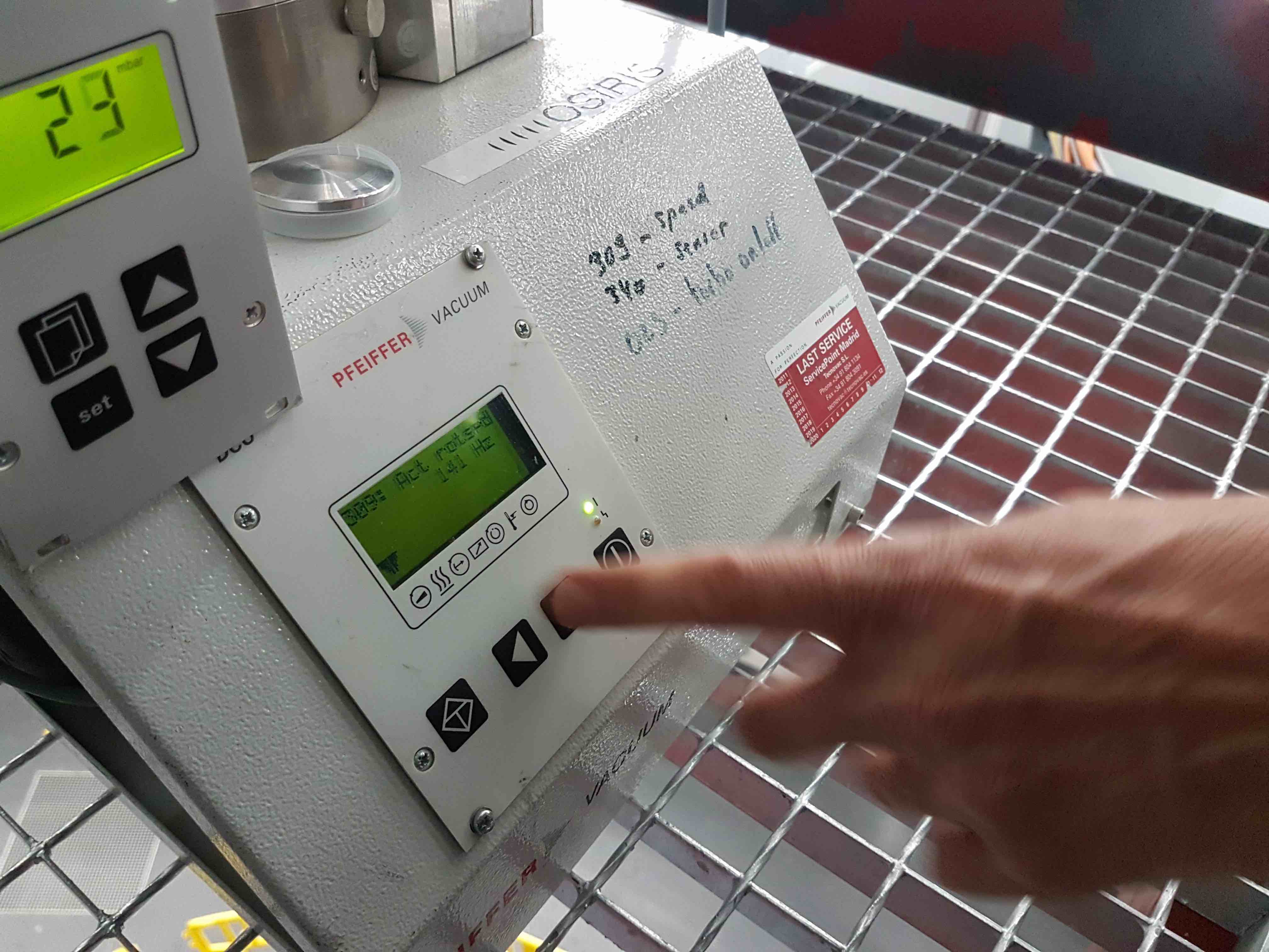
- When the turbo speed is at its maximum value of 1500 Hz and the pressure on the pump gauge falls to the low e-5 mbar range, open the valve to the HiPERCAM vacuum manifold. You should see the pressure on the gauge rise slightly and then quickly drop again.
- If the HiPERCAM vacuum manifold is at atmospheric pressure, follow the above procedure, but open the valve to the vacuum manifold before you power on the vacuum pump. If you don’t do this, and you open the manifold valve when the turbo is up to speed, you will damage the pump with the sudden rush of air.
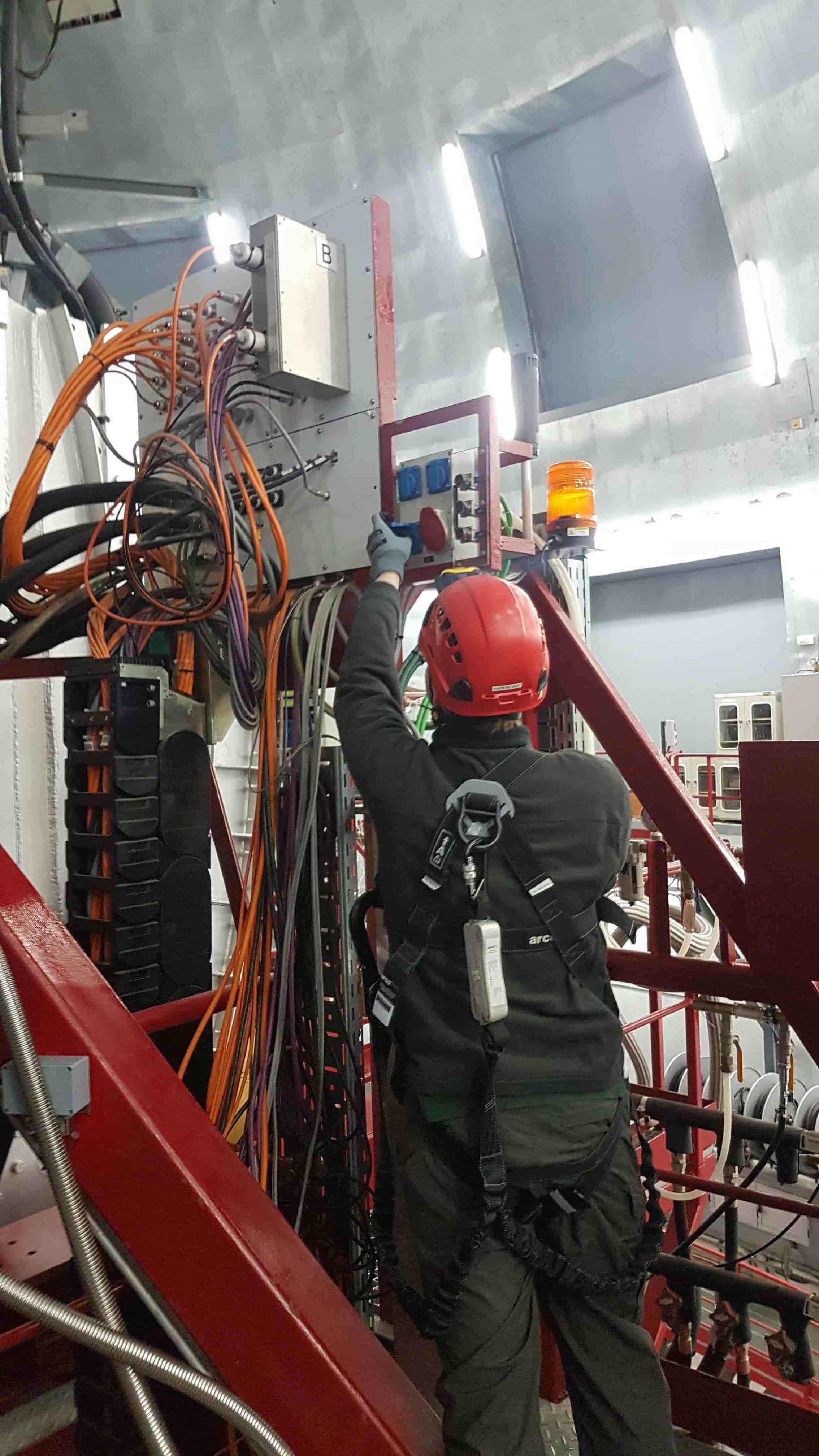
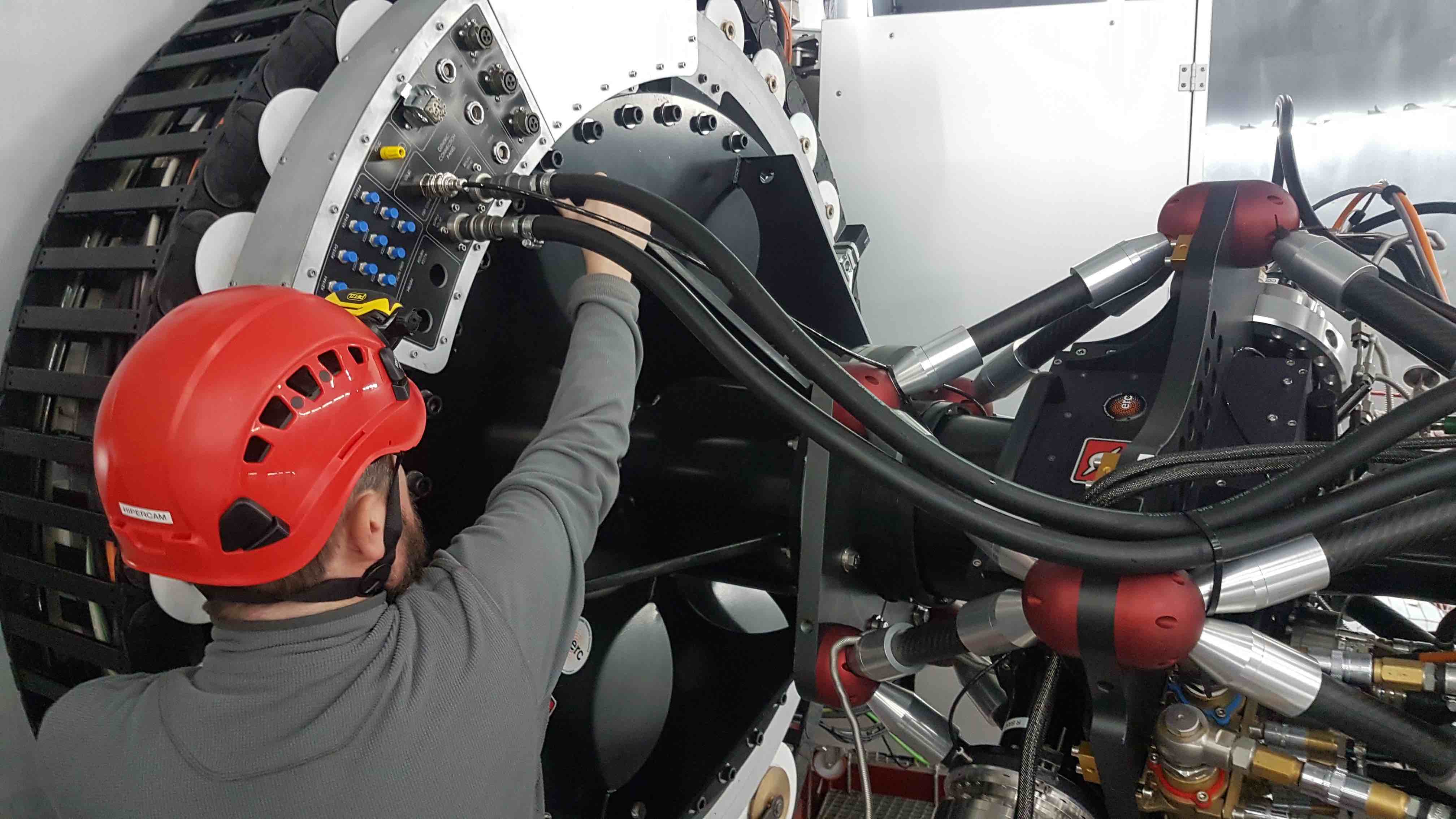
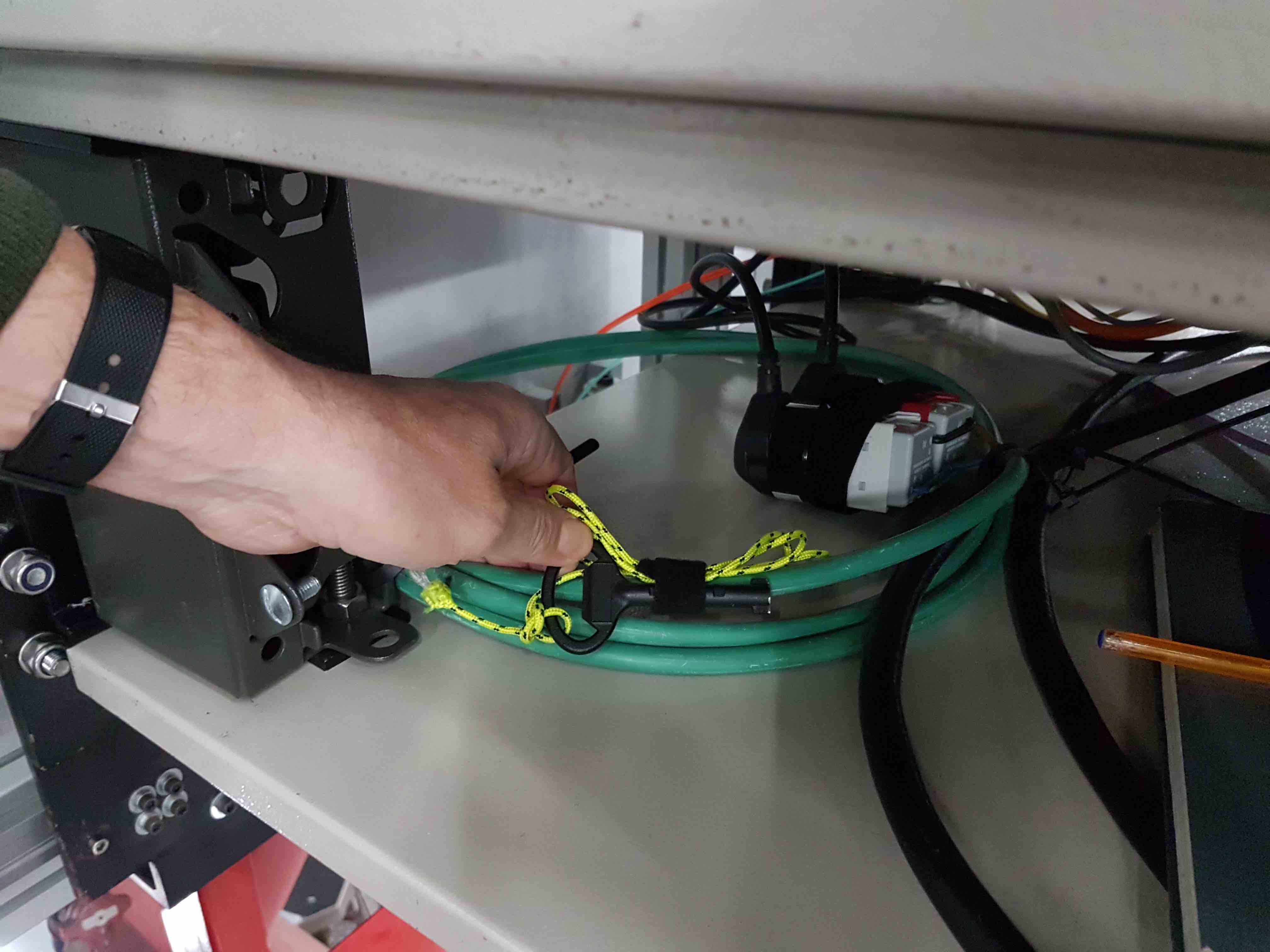
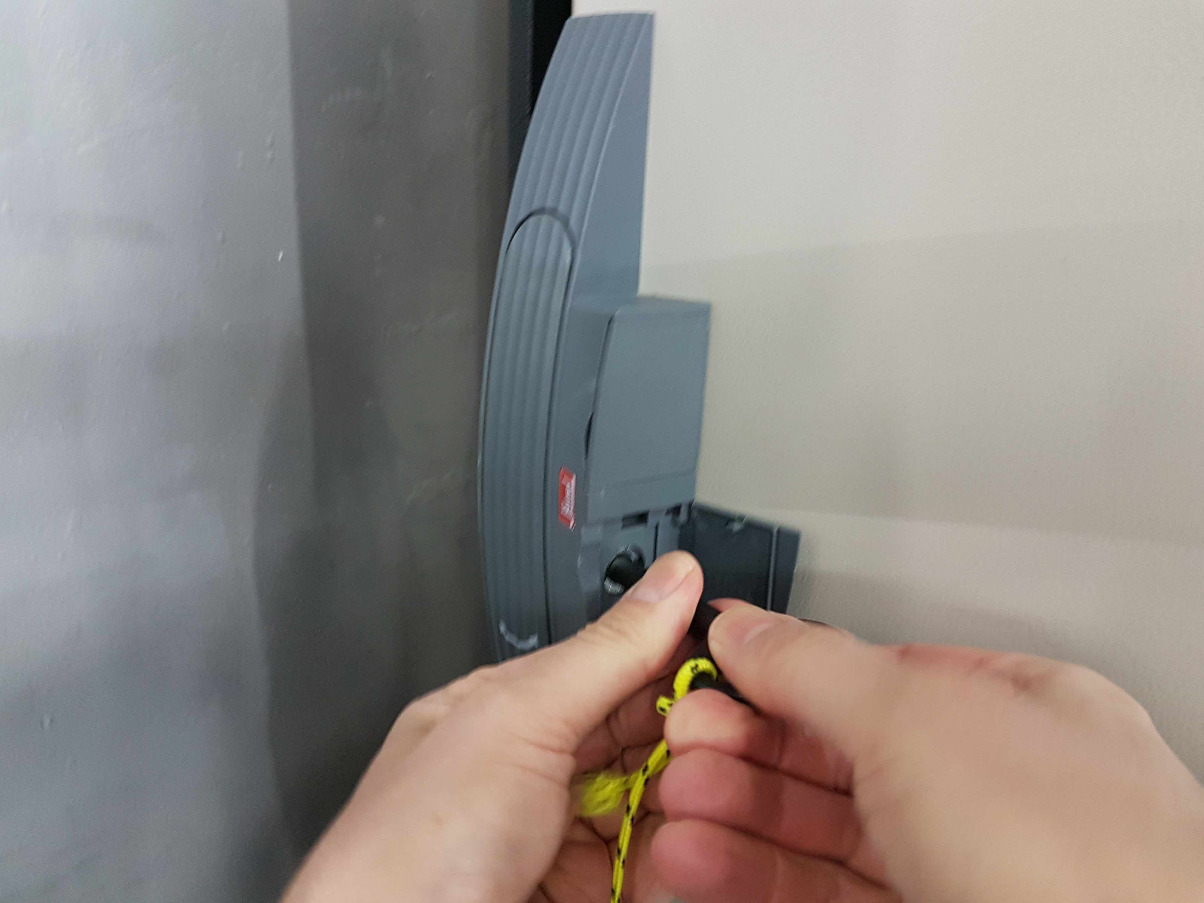
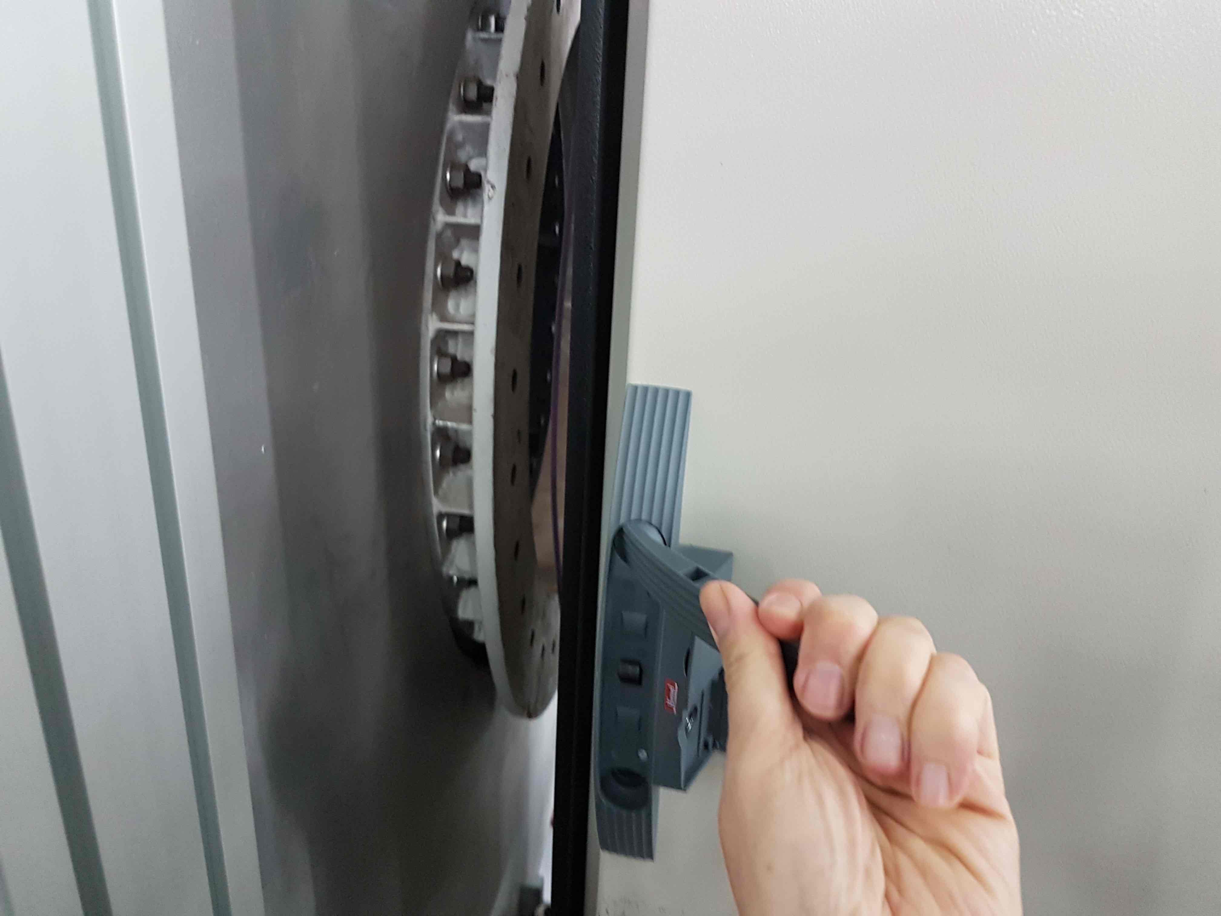
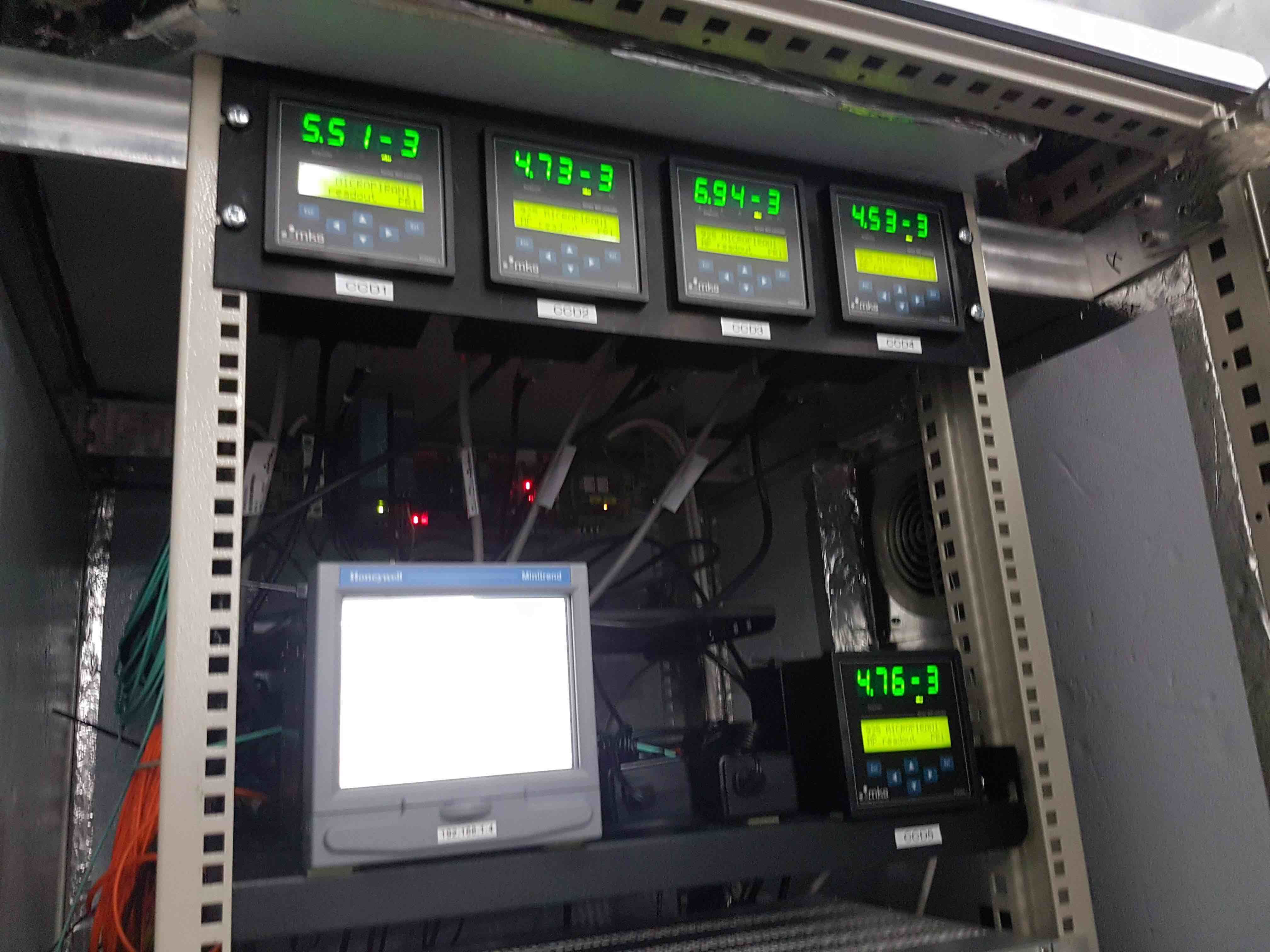
- Before you can open the vacuum valves on the CCD heads, you need to inspect the head pressures, which are displayed in the HiPERCAM electronics cabinet. Open the door of the cabinet using the key attached to the yellow string lying on the bottom shelf of the cabinet. (Be careful not to lose the little loop of black velcro used to attach the key and string to the green cable.)
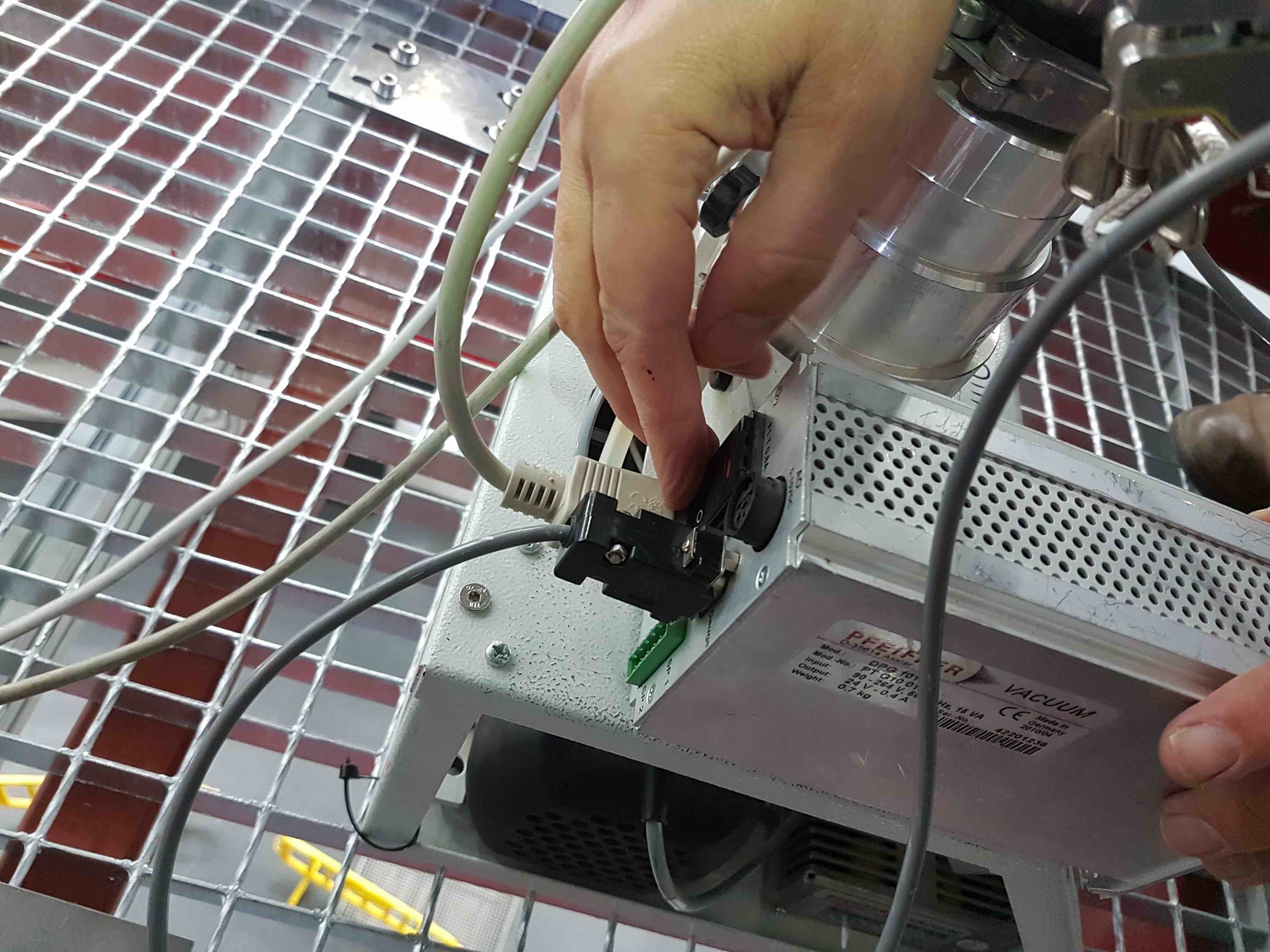
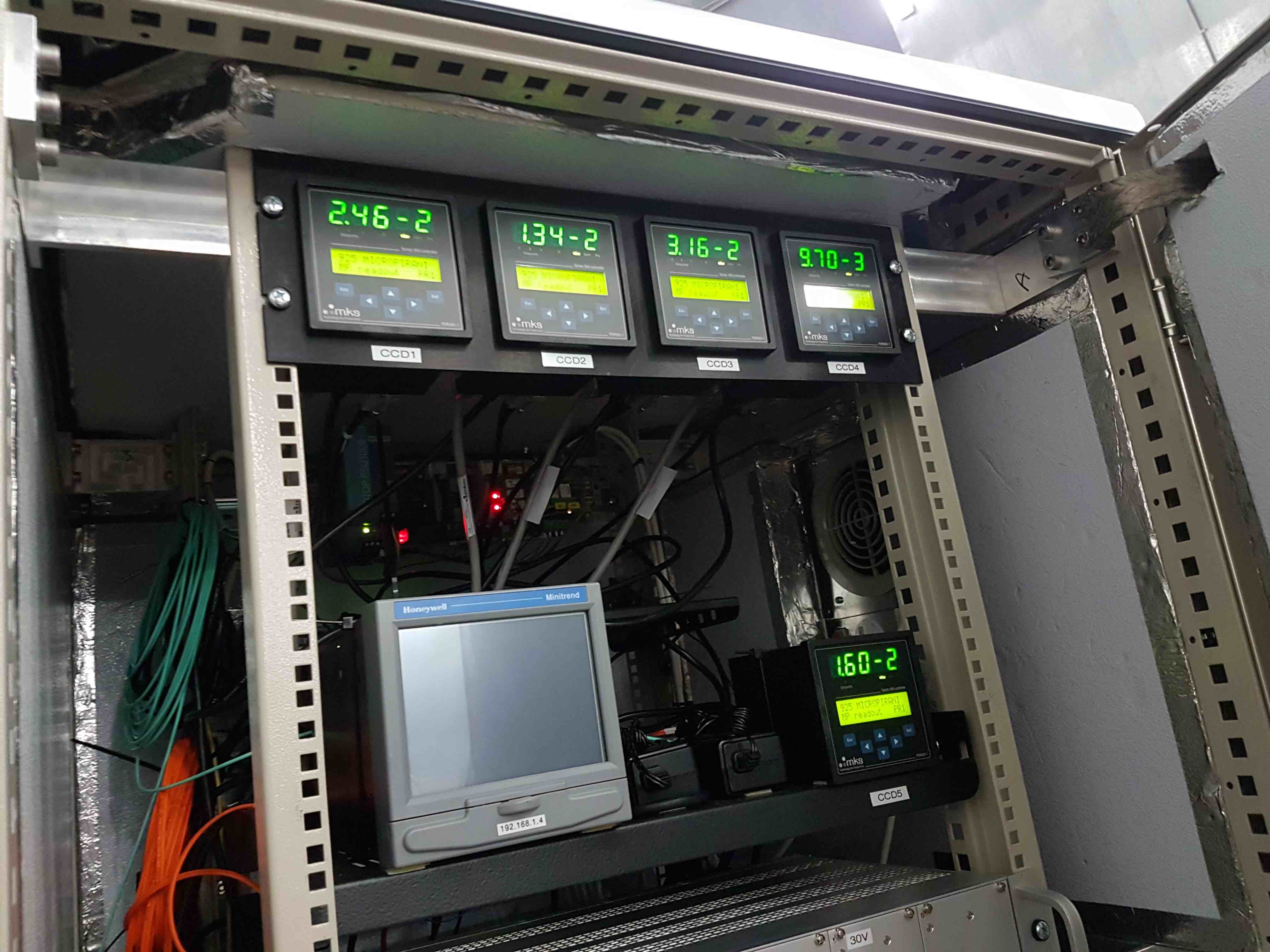
- If they are not already switched on, power on the vacuum gauge controllers located near the top of the cabinet by reaching with your hand behind each controller and pressing the toggle switch. If all is well, the pressures in each head should be in the e-2 mbar range.
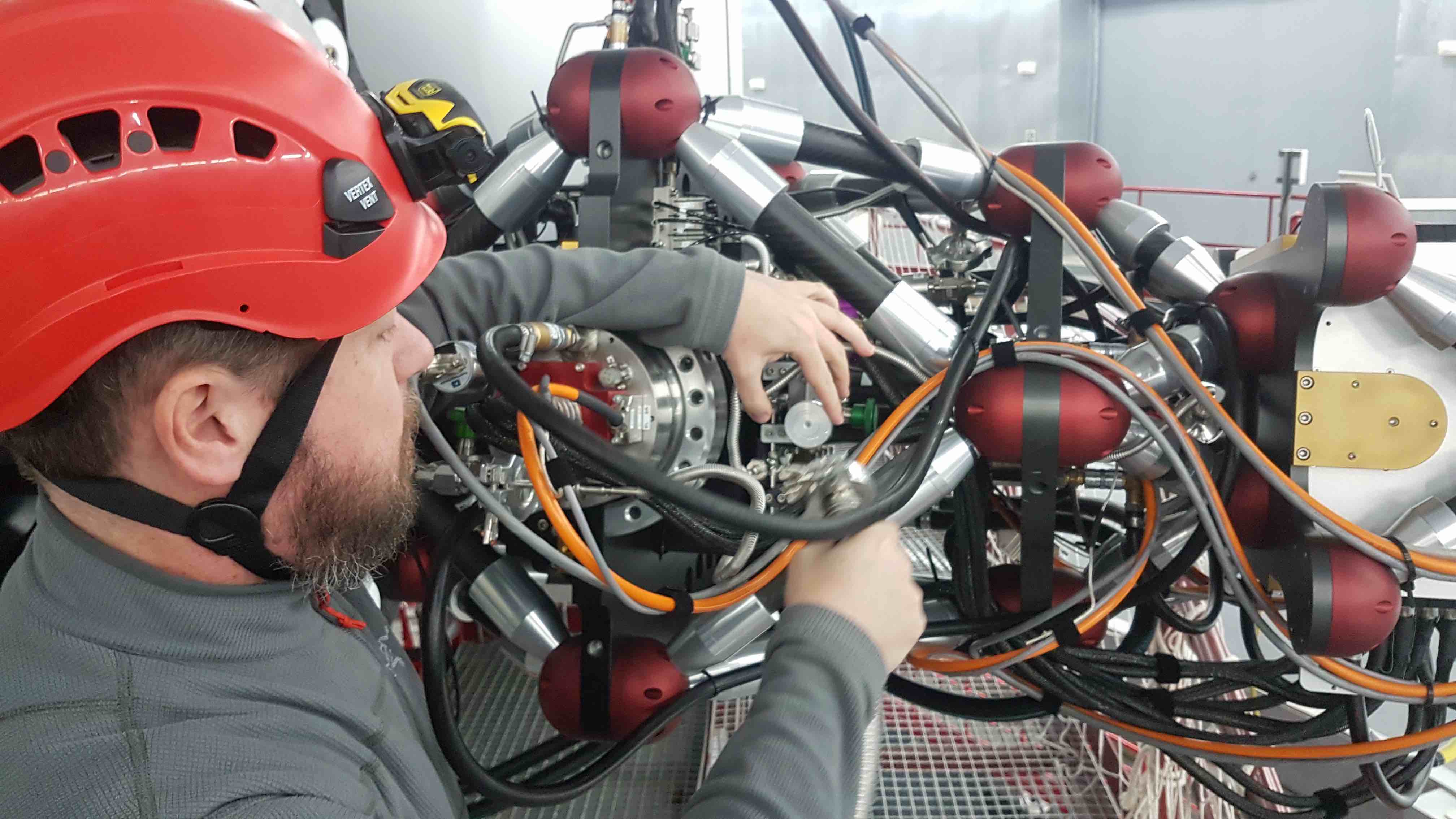
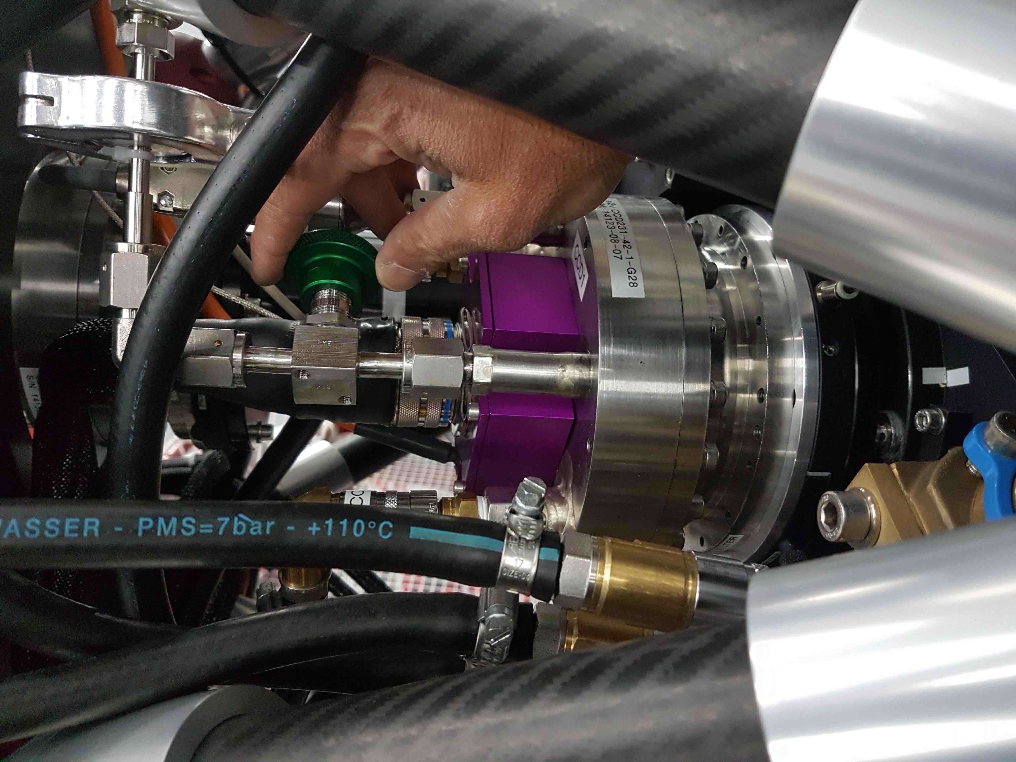
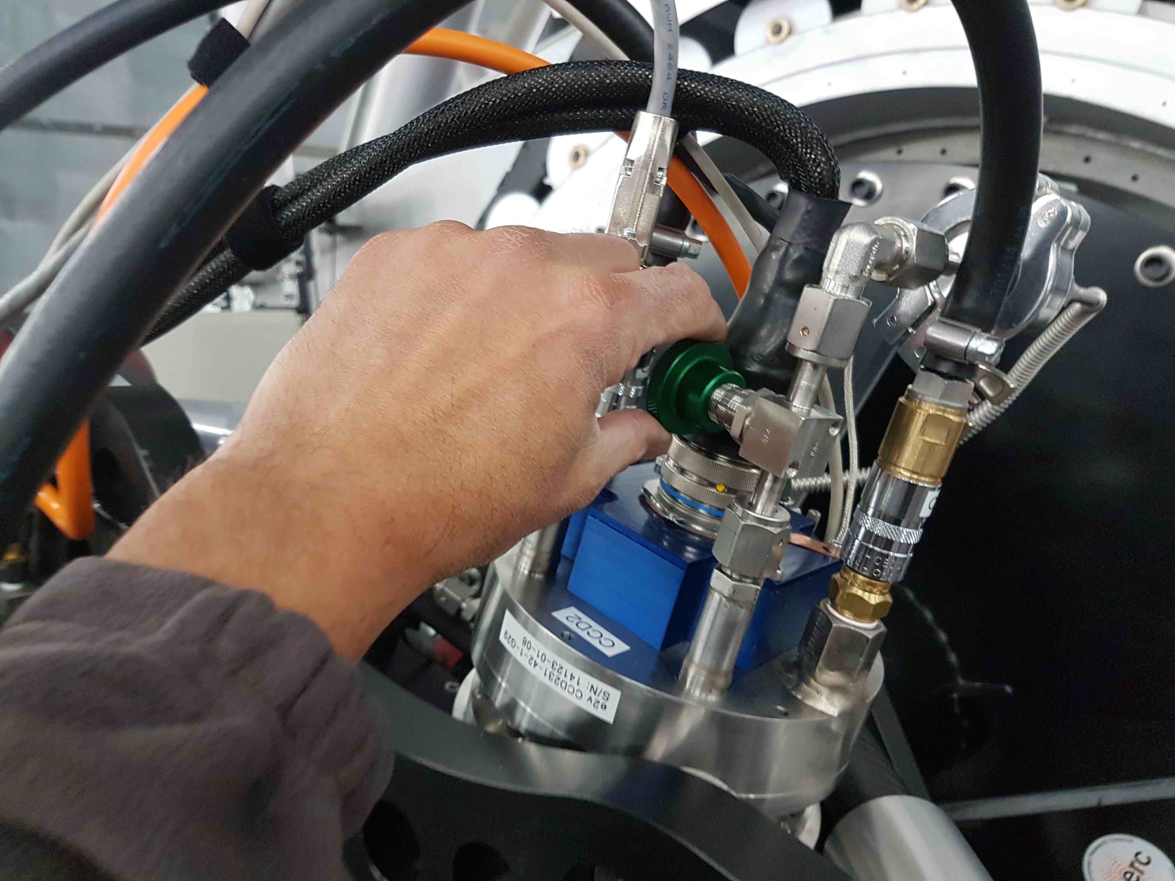
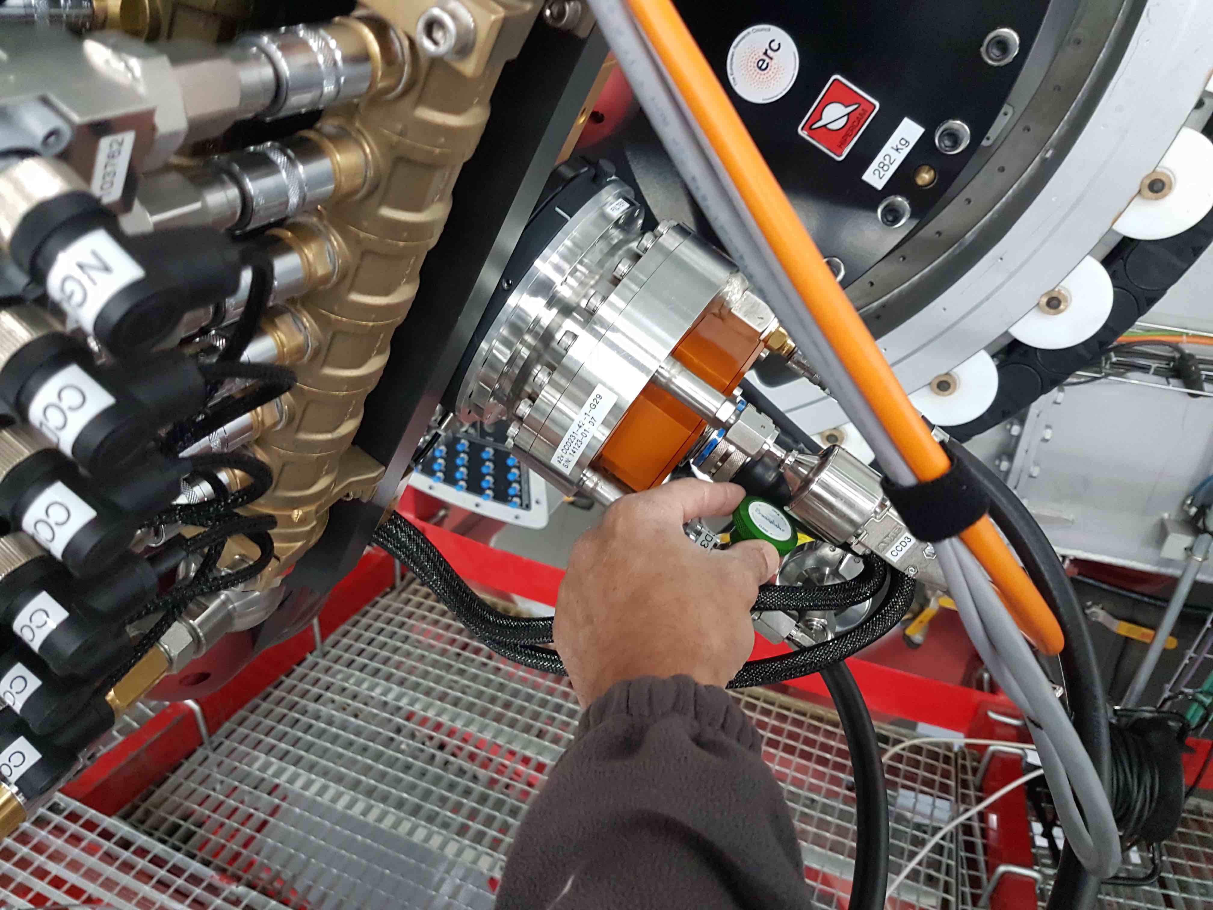
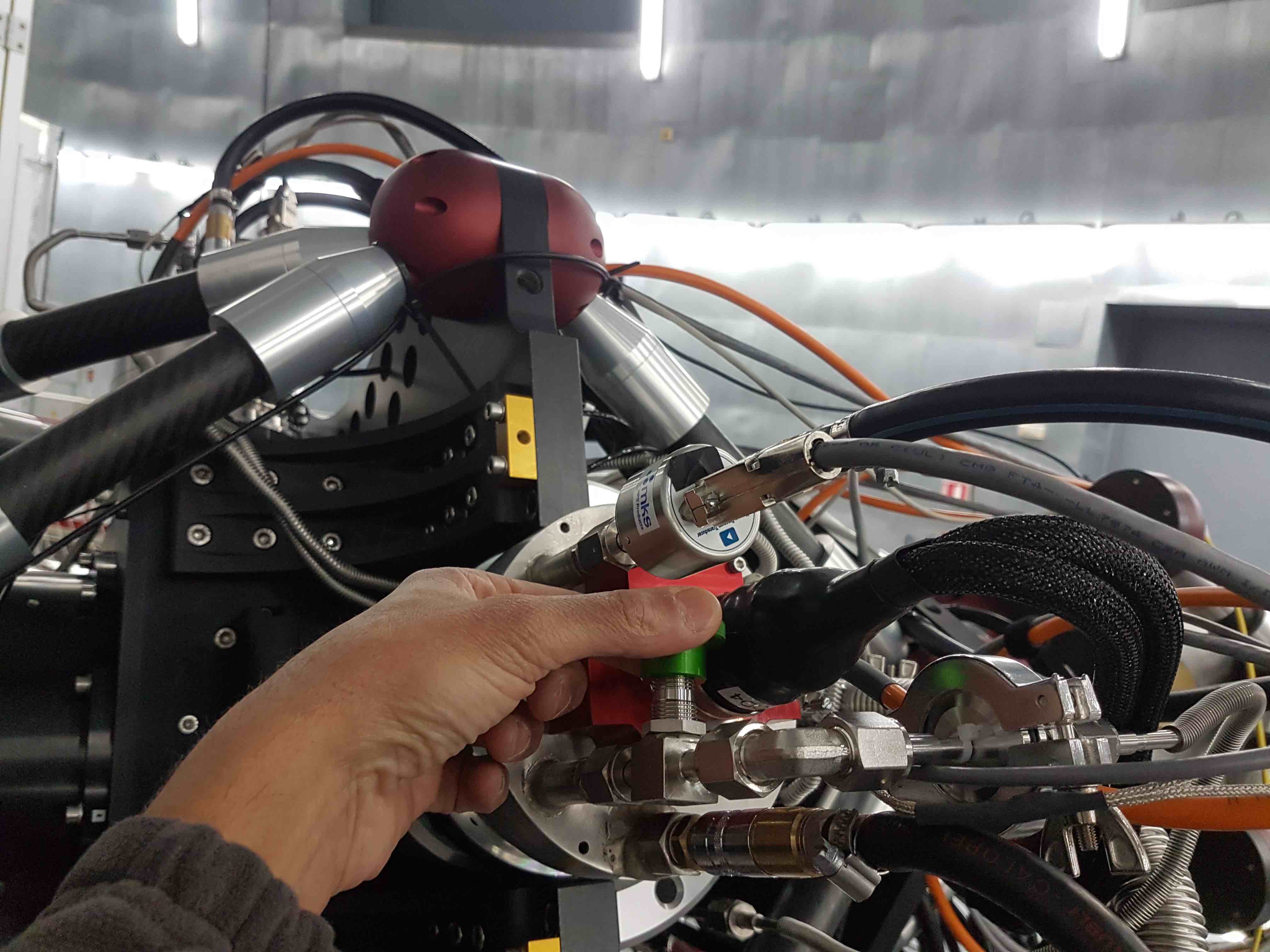
You are now ready to open the vacuum valves to the CCD heads. For the safety of the CCDs, this should be a two-person job, with one person opening the valves and the other watching the vacuum gauges. Choosing the CCD head with the highest pressure, slowly open the valve on the head, but do not open it fully yet. If the person watching the gauge sees the pressure rise, shout out to the other person to close the valve immediately and then check the pump and vacuum pipe connections for problems. If, on the other hand, the pressure drops, then shout OK and continue to open the valve until you feel it go loose, at which point you should start closing it until you feel resistance and then stop. Then move onto the CCD head with the next highest pressure. Only open the valve to this head if the pressure in the first CCD head is approximately equal to or lower than the head to be opened. In this way, one can avoid reverse pumping from one CCD head to the other. Repeat the procedure until all five CCD heads are open - you can identify which CCD head is which using the sticker on each head or the colour-coded anodised PCB boxes on the rear of each head.
u CCD1 purple g CCD2 blue r CCD3 orange i CCD4 red z CCD5 dark red
The CCD head pressures should drop steadily, getting into the e-3 mbar range within a matter of minutes and then into the e-4 mbar range after a few hours. When the CCDs reach the low e-3 mbar range, it is safe to begin cooling them.
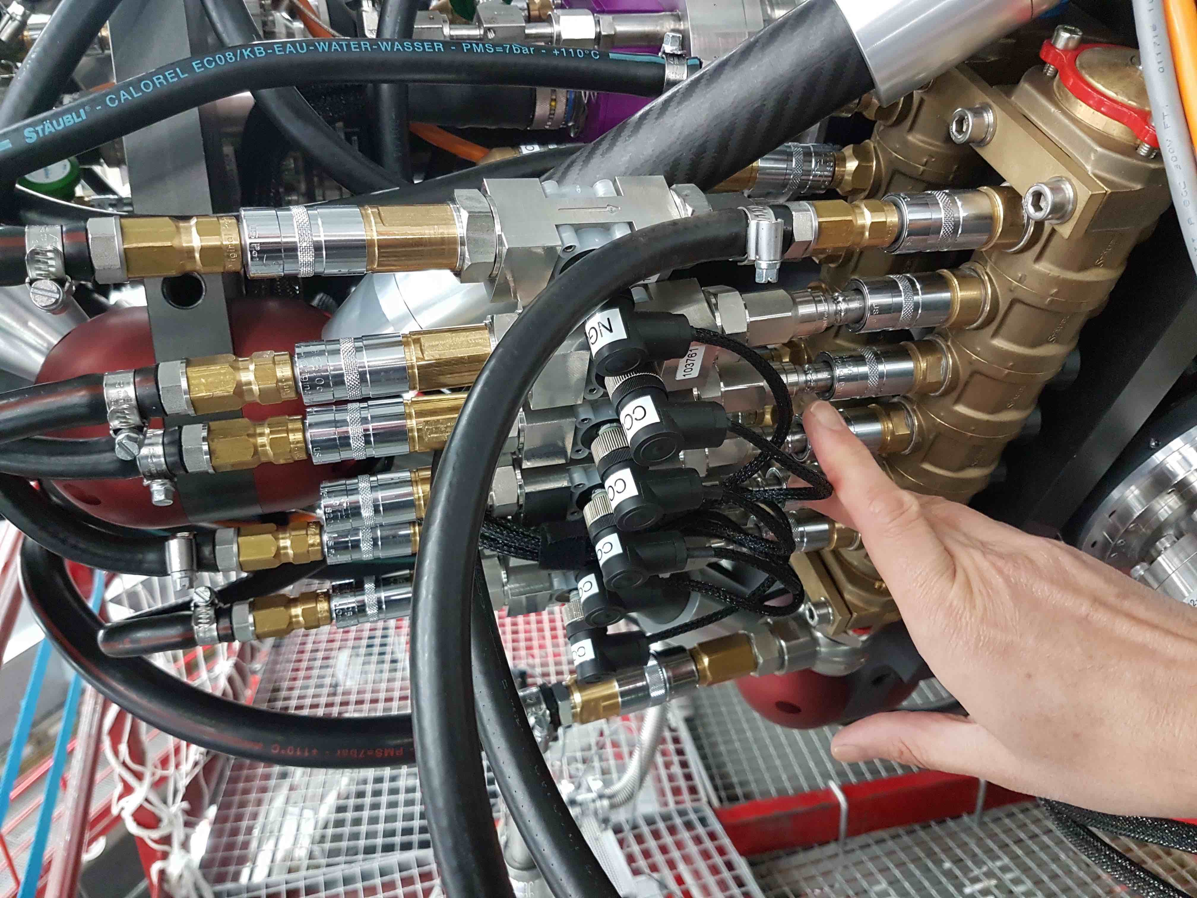
The HiPERCAM CCDs are cooled by peltier coolers that are themselves cooled by the GTC +5degC water/glycol chiller system. The CCD heads are cooled in parallel, fed by two 6-way manifolds mounted on the instrument. The cooling pipes are colour coded, with blue markings indicating the cold water flow and red markings the hot water return. Each of the 6 parallel arms in the cooling circuit is equipped with a flow sensor that cuts power to the associated peltier if the flow falls to zero. As a backup, the power is also cut to the peltiers if their hot side goes above a temperature of +50degC.
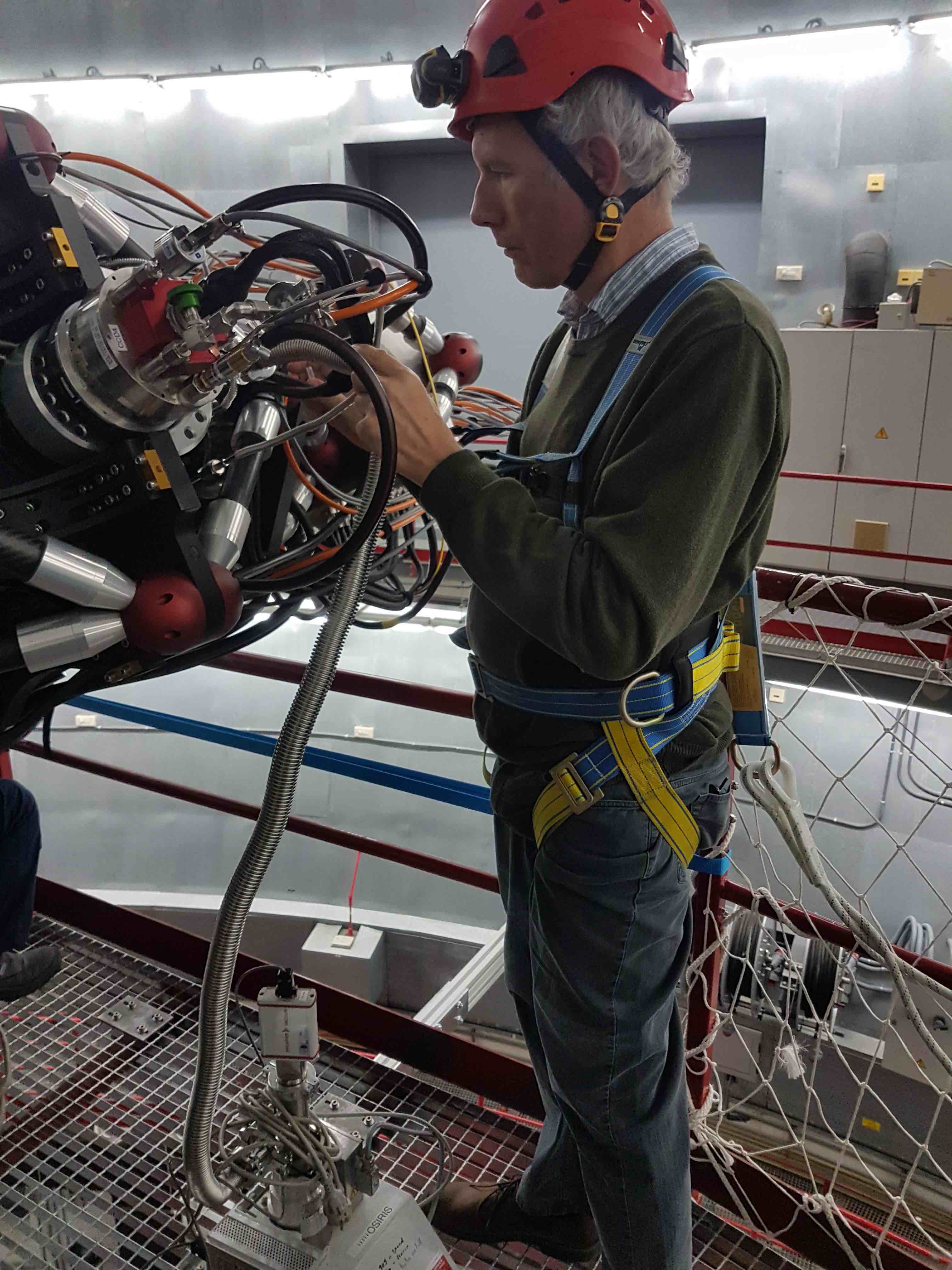
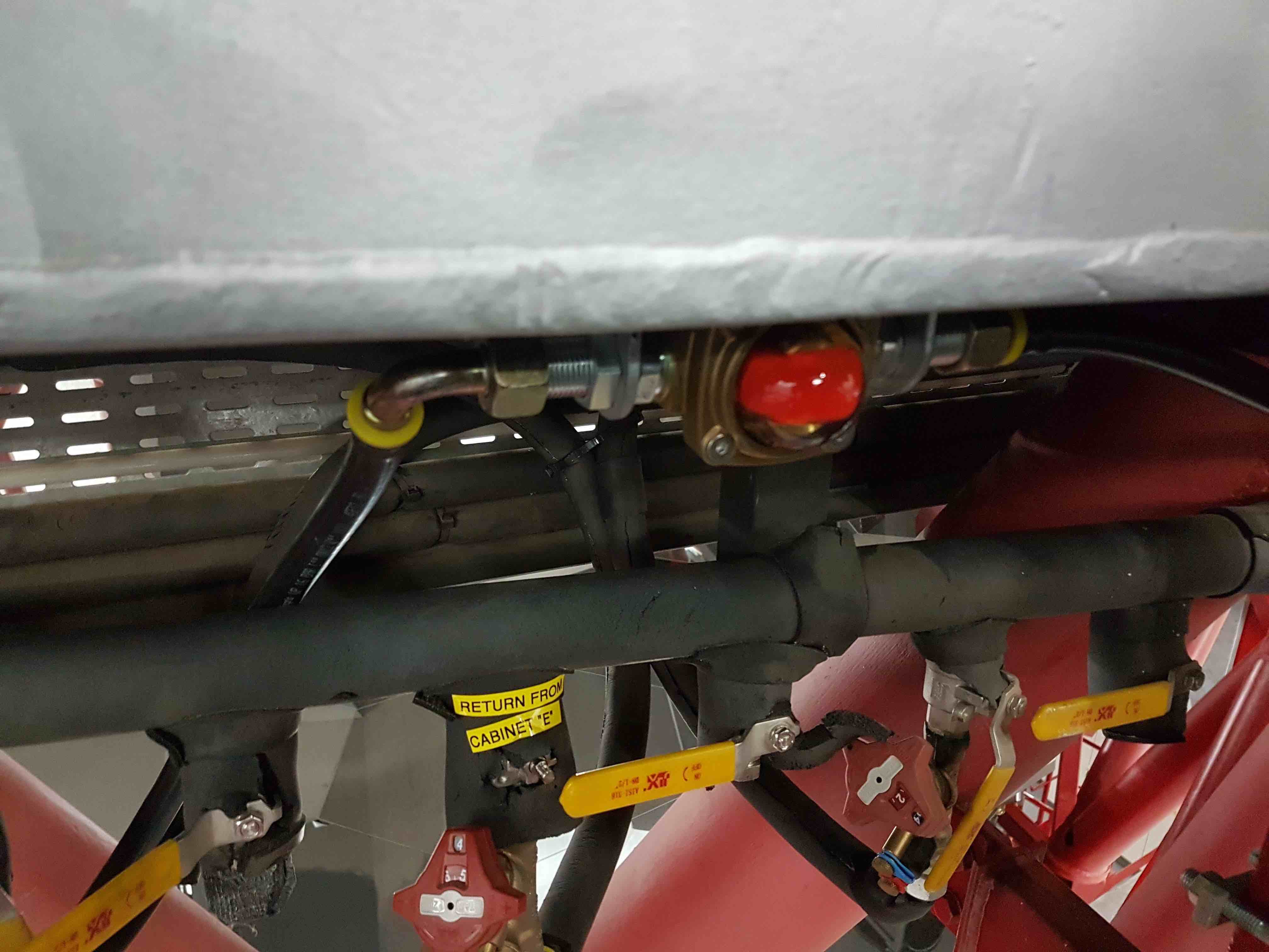
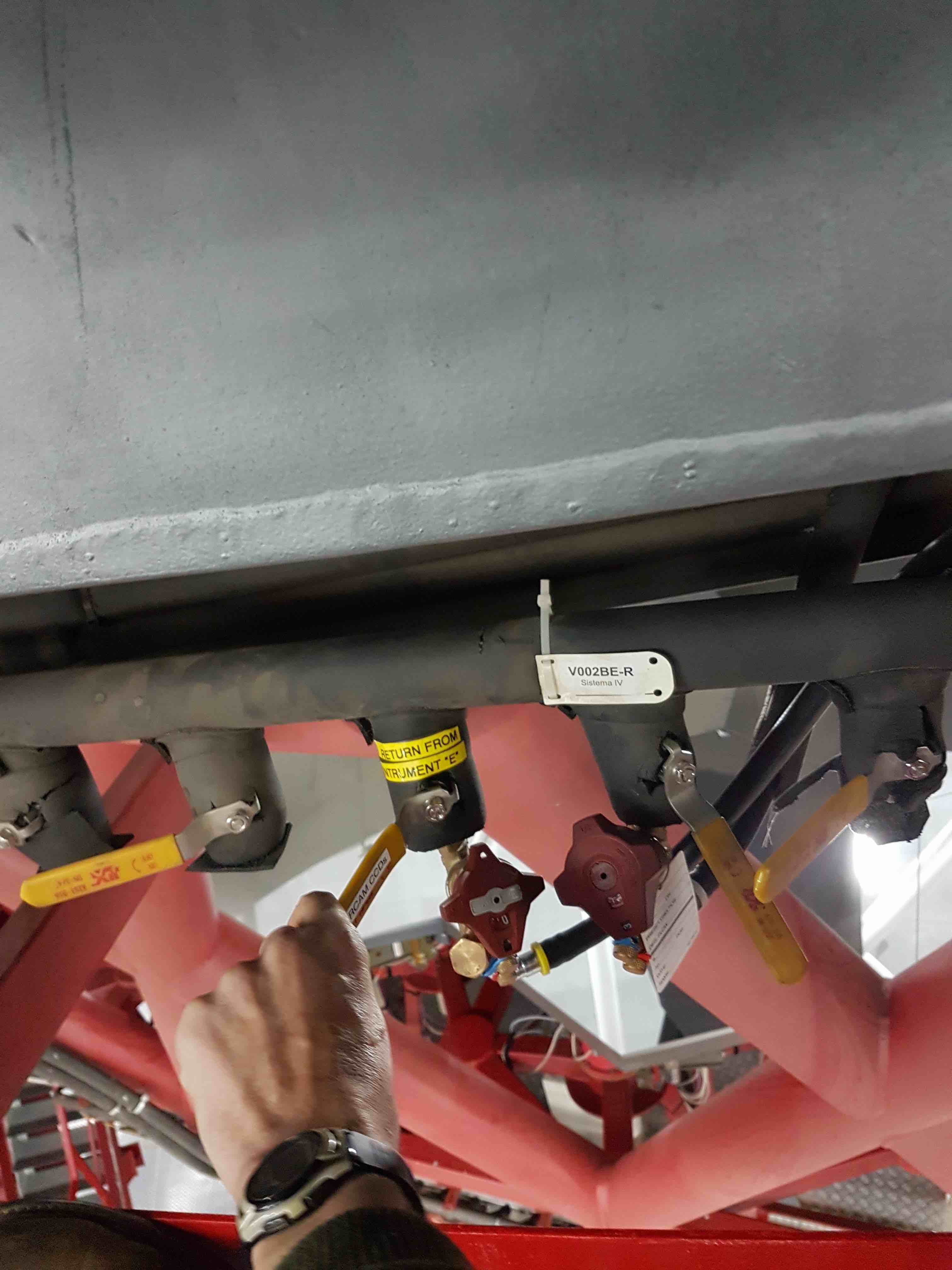
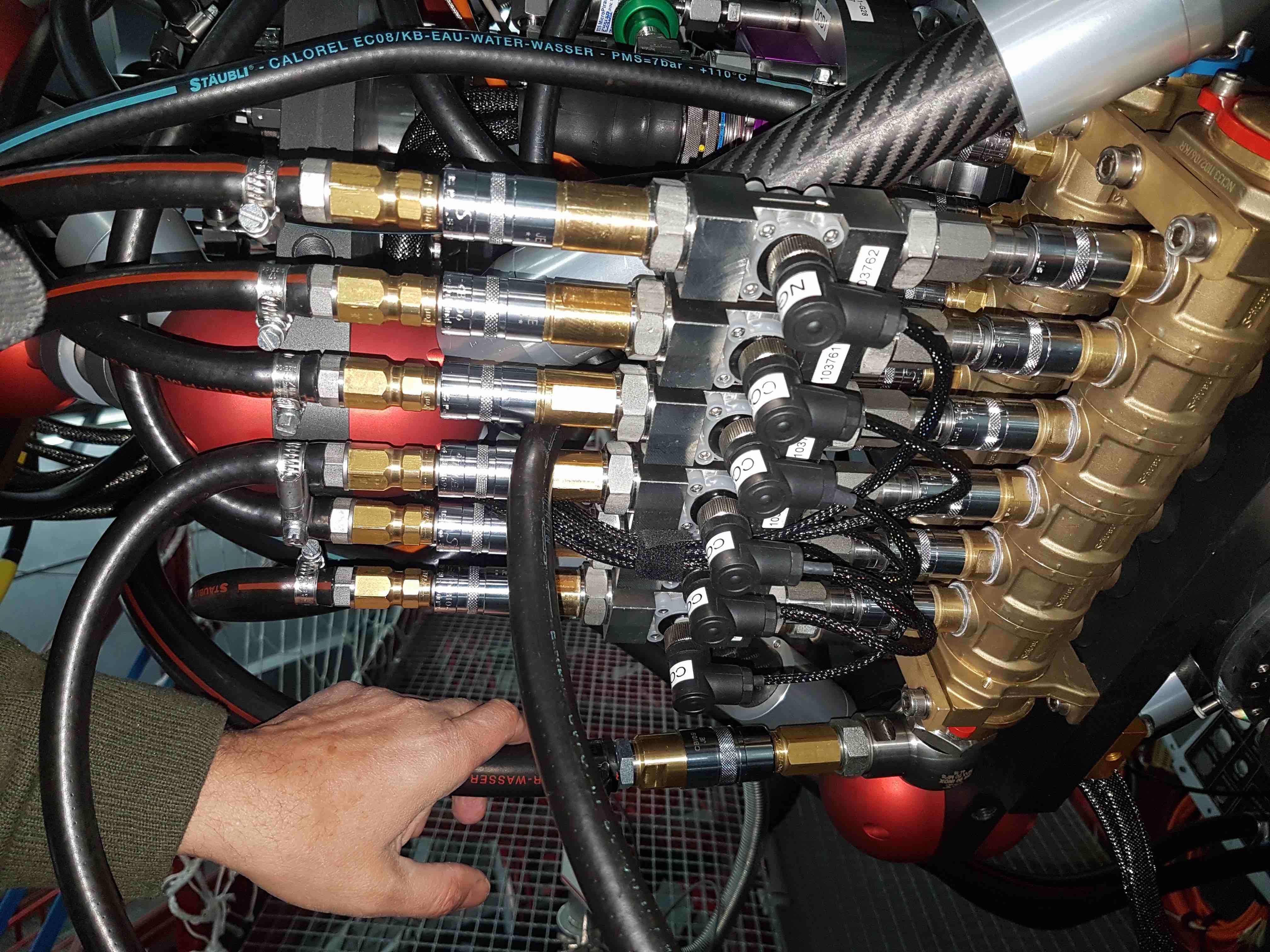
On first connecting HiPERCAM to the GTC cooling circuit, it is essential to ensure that no water bubbles pass through the HiPERCAM flow sensors, as this could damage them. So, disconnect all 6 of the flow sensors from the manifold and attach a single hose to the manifold to make a circuit. (You may actually find it easier to remove the hoses from the flow sensors rather than disconnect the flow sensors.) Then turn on the coolant flow by turning the yellow valve lever marked HiPERCAM CCDs underneath the rotator by 90 degrees so that it is pointing down to the ground. You can tell that the coolant is flowing by inspecting the red propeller mounted above it.
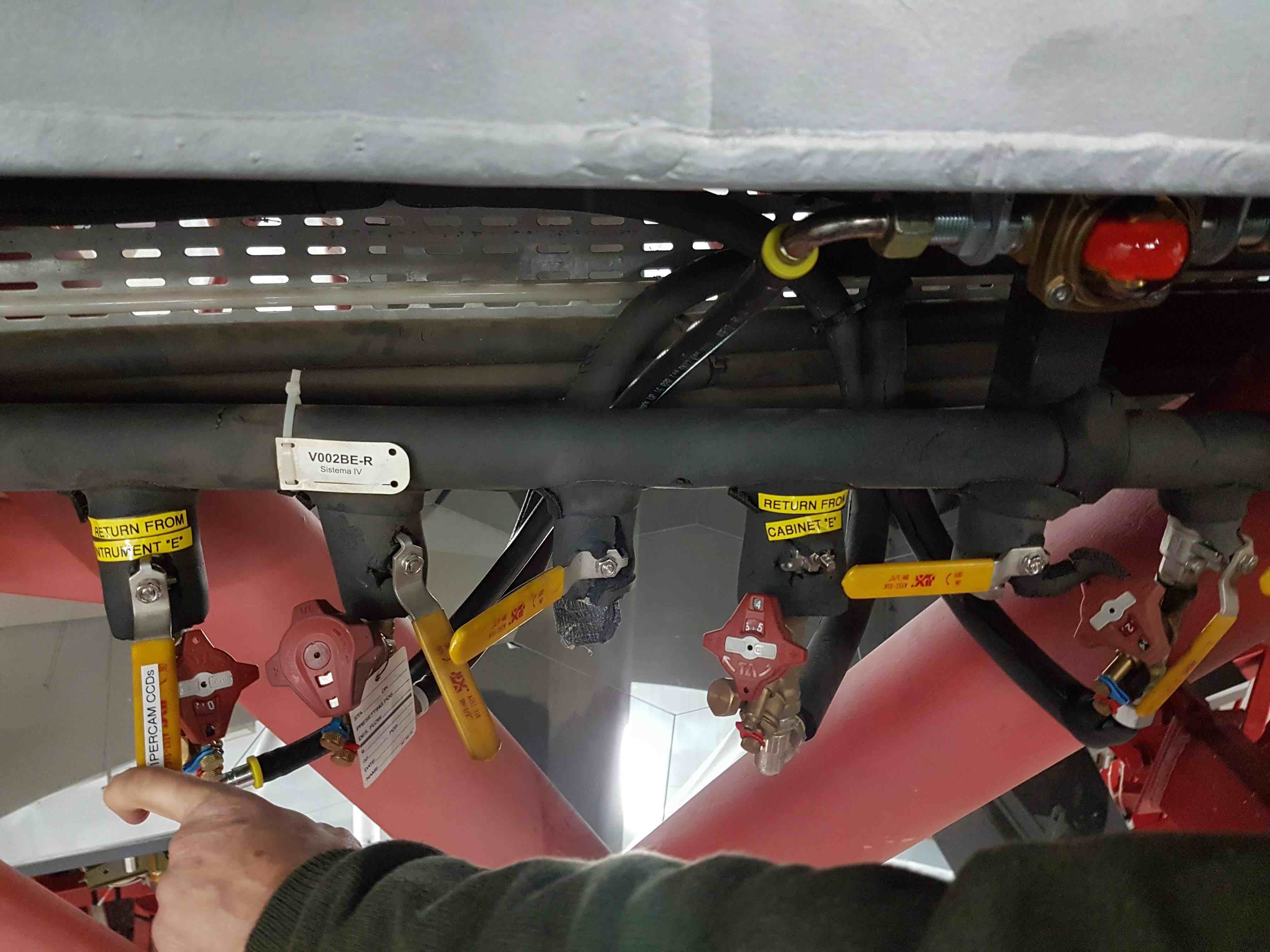
- Watch the red propeller for a few minutes, waiting for all of the air bubbles to pass through the system. Then close the yellow valve lever, reconnect the 6 flow sensors to the manifold and then open the yellow valve lever again.
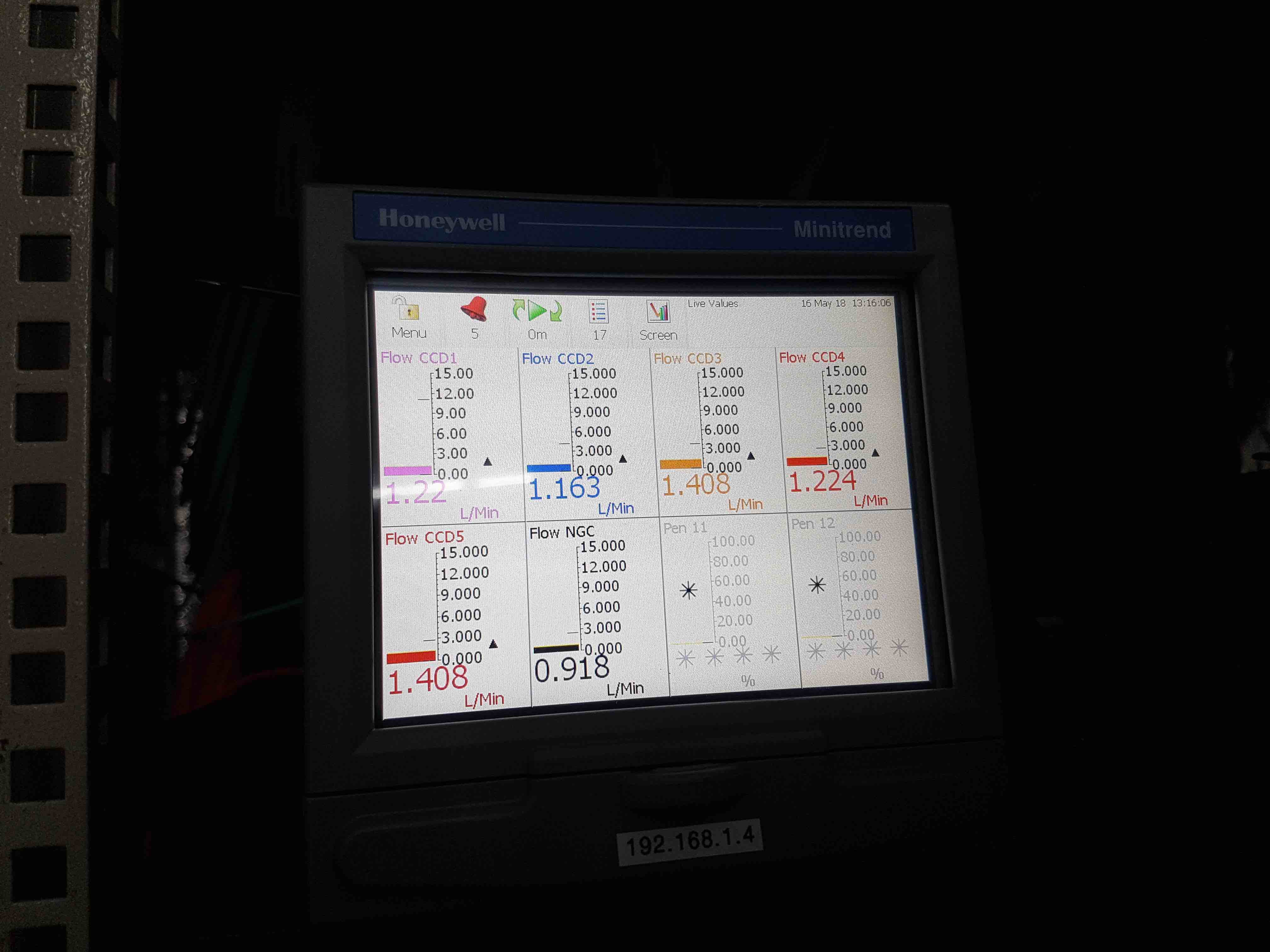
- Now turn on the Honeywell data recorder in the electronics cabinet by connecting the IEC power cable at its rear. There is no power switch on this unit, so it will turn on immediately. Once the Honeywell has booted up, which takes a few minutes, the flow rates through each CCD of HiPERCAM, as well as the NGC, should be indicated on it. The values should all be approximately 1 litre/min. If no flow is indicated, check that the lap-top style power supplies for the flow sensors and relays lying to the right-hand side of the Honeywell are plugged in.
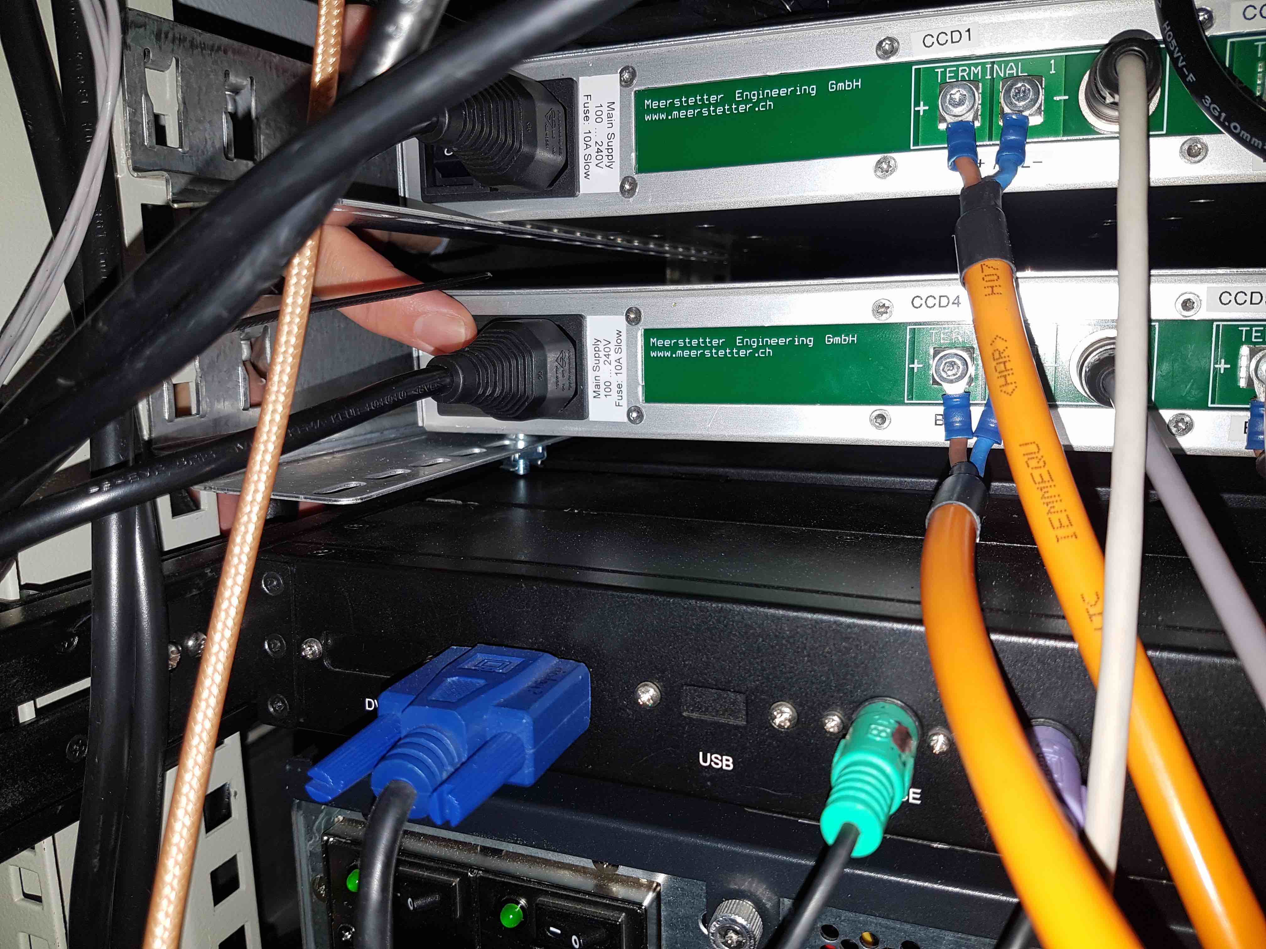
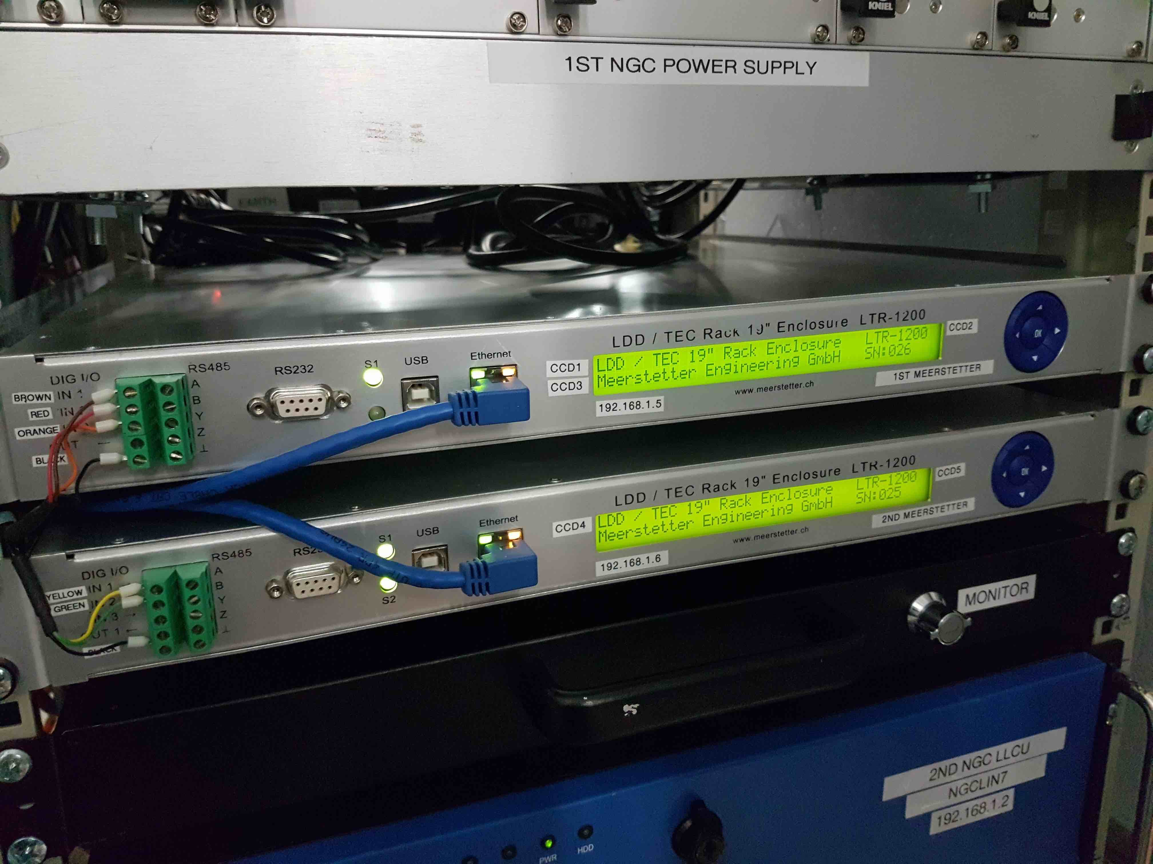
- Finally, turn on the two Meerstetter peltier controller units by reaching behind them and pressing the power toggle switch.
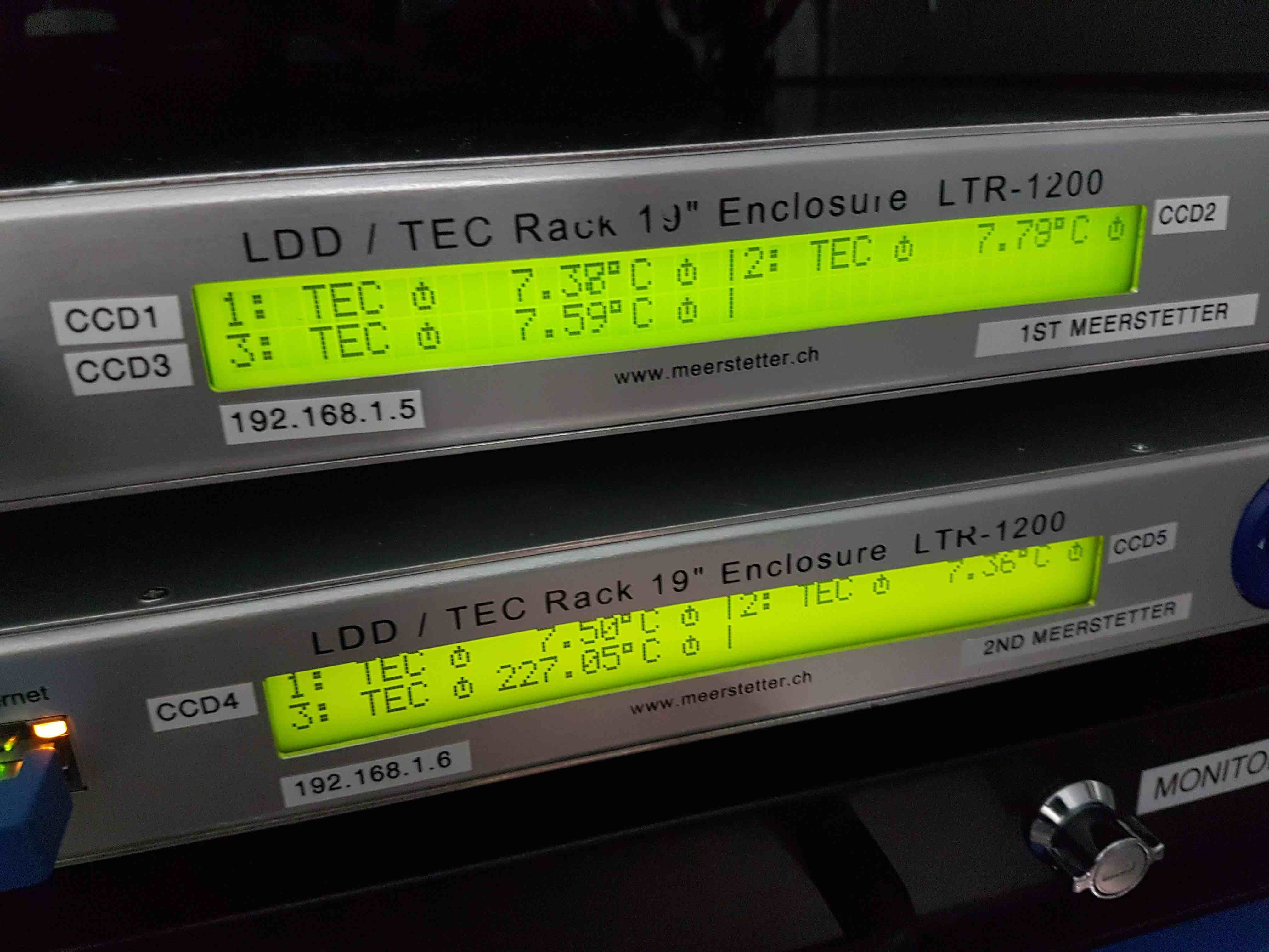
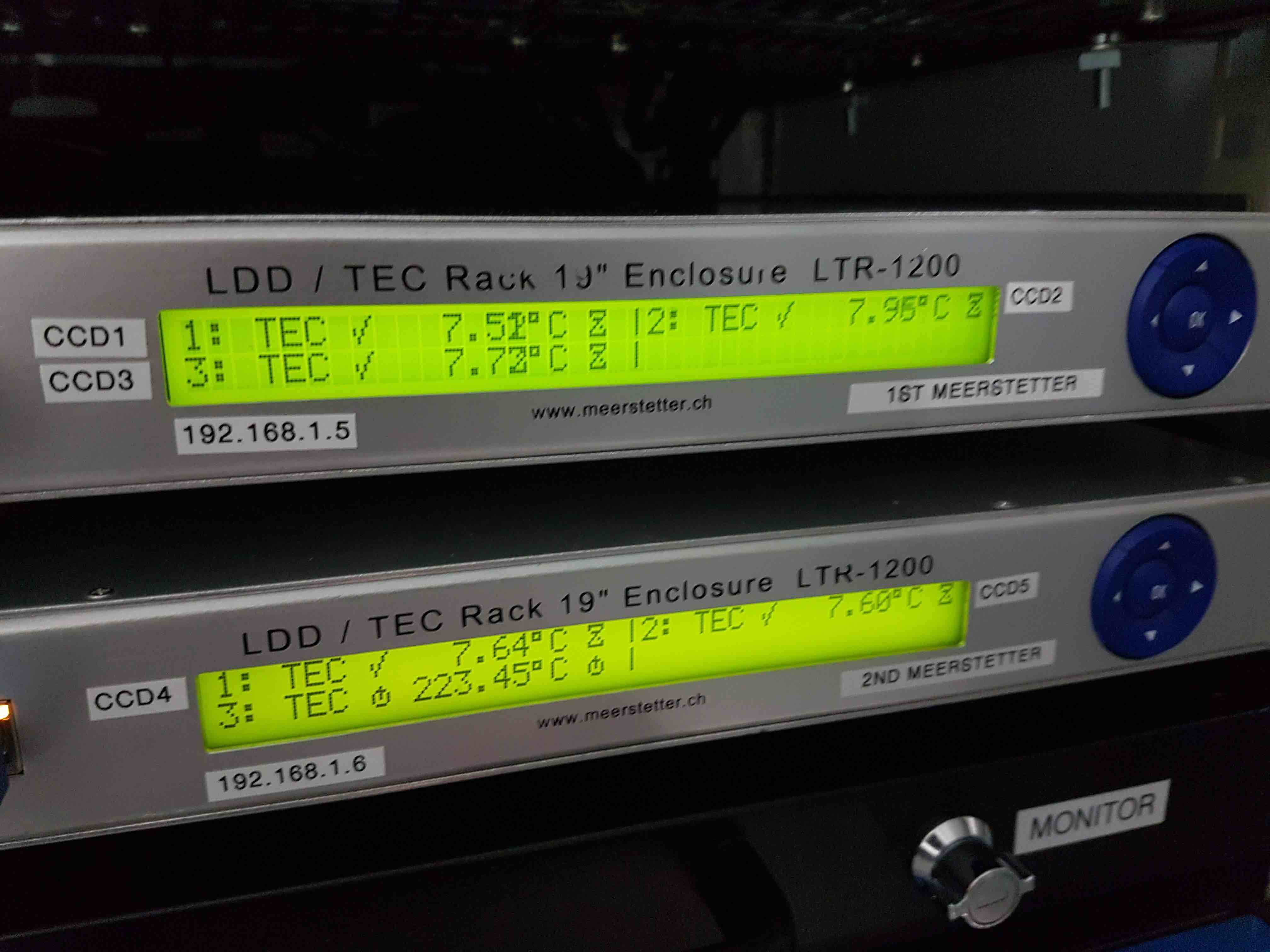
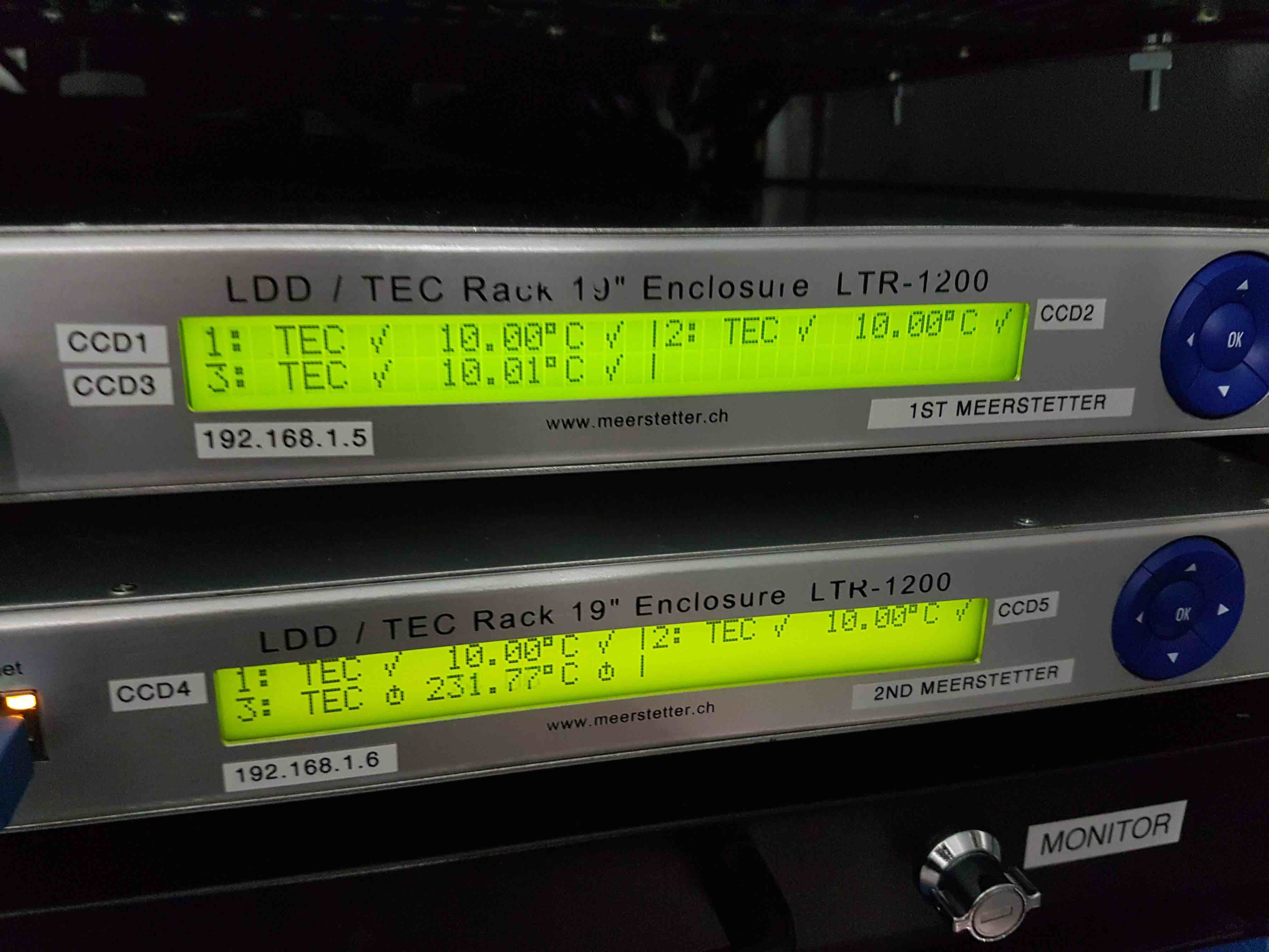
- Once the Meerstetters have booted up, press the blue round OK button on the right hand side of the front panel to display the CCD temperatures. If the coolant is not flowing, a circular power symbol is indicated on both sides of the CCD temperatures. If the flow is turned on, a tick appears on the left-hand side of each CCD temperature, and either an hour-glass symbol or a tick appears on the right-hand side of each CCD temperature, depending on whether or not the CCD is at its target temperature.
Now set the CCD target temperatures, which are -90degC for CCDs 1, 4 and 5, and -88degC for CCDs 2 and 3. You can set the temperatures locally using the Meerstetters, or remotely using
hdriver.To set them locally:
- Press the left arrow on the blue control panel as many times as necessary to get to the top-level LDD/TEC screen.
- Press the middle blue OK button to display all 3 CCD temperatures.
- Press the right arrow to get to the LTR settings screen.
- Press the down arrow to get to the Terminal 1 page, i.e. CCD1.
- Press the right arrow to get to the temperatures menu.
- Press the down arrow 5 times to get to the Target object temperature setting.
- Press the middle button to enable the temperature to be changed.
- Press the up and down arrows to change the value of the digit, the left and right buttons to change the digit, and the middle button to set the value.
- Press the left arrow to return to the Terminal 1 page and then the down arrow to enter the Terminal 2 page, i.e. CCD2. Repeat the above to change its Target object temperature, and then repeat again for Terminal 3, i.e. CCD3.
To set them remotely:
- On
hdriver, click on the Settings menu at the top and select Expert Level 1. An additional button will appear towards the top-left hand side of the GUI labelled CCD TECs. - Click on the CCD TECs button to enter the temperatures page. Enter the target temperature setting for CCD1, for example, remembering to press carriage return after you have entered the value. Then press the associated Reset button to set the target temperature. Repeat this operation for the other CCDs.
The Meerstetter peltier controller has a ramp function that has been set to cool down (or warm up) the CCDs at a rate of 0.1deg/s. Therefore, it takes approximately 15 minutes to cool the CCDs down. The power output of the Meerstetters has been limited to 85% of the maximum power that can be safely applied to the peltiers. This is the reason why the set temperatures of CCDs 2 and 3 are only -88degC: if set to -90degC, these CCDs would struggle to maintain this temperature and permanently draw the maximum power available, potentially shortening the lifetime of the system.
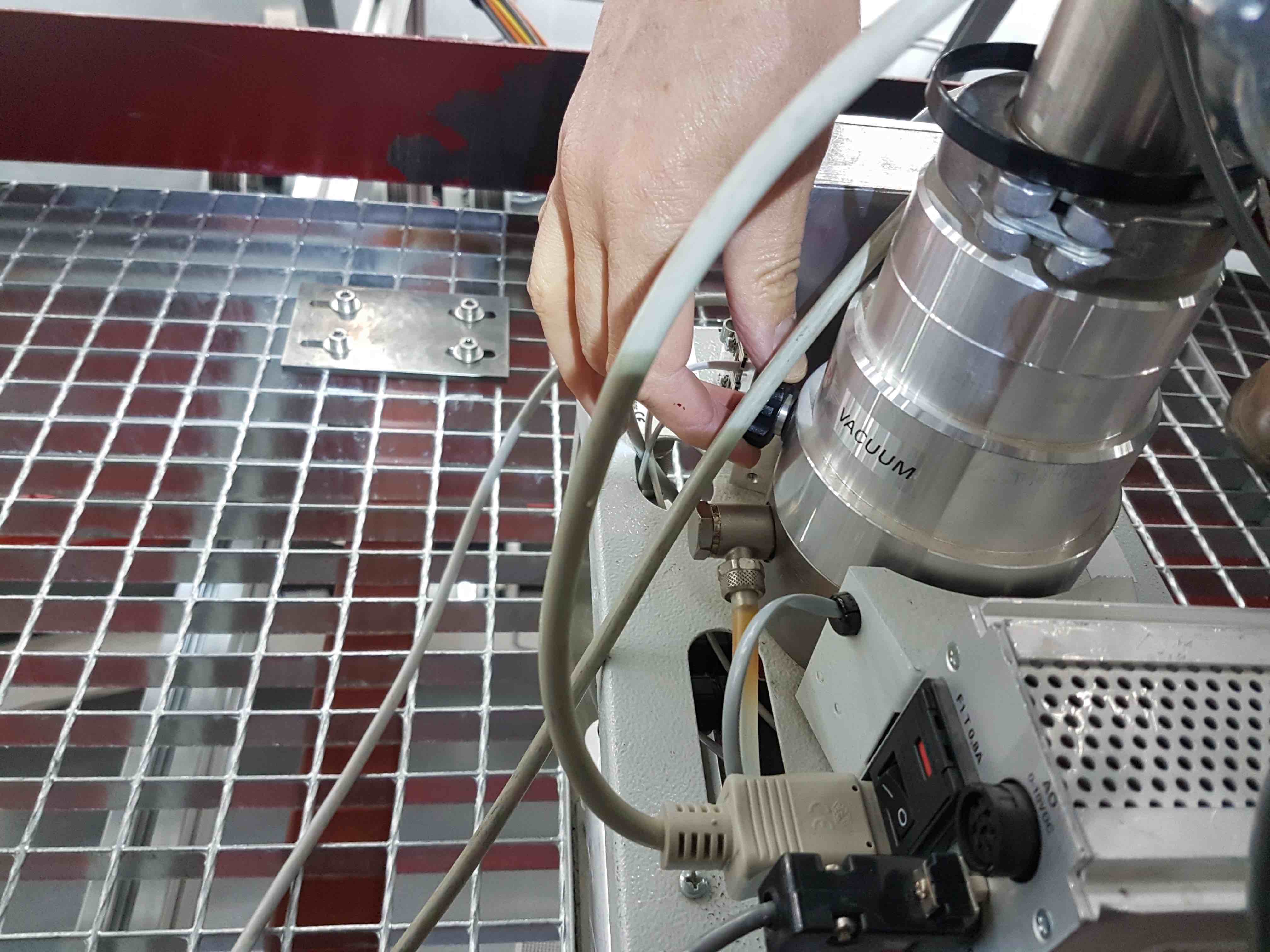
To prevent condensation forming on the exterior surfaces of the CCD head windows, HiPERCAM employs a nitrogen-gas flushing system, fed by the observatory supply via a 5-way gas manifold mounted on the large central plate on the instrument. To check that the gas is flowing, remove one of the black gas pipes going into one of the CCD heads by simultaneously pulling the pipe and pushing the shoulder of the self-sealing connector. Place the pipe near your lips - you should be able to feel a very gentle breeze. If you can’t, check with the GTC staff to see if the gas supply has been turned on. If it hasn’t, make sure you disconnect the main gas pipe feeding the manifold prior to turning the supply on, as otherwise you may send high pressure gas into the manifold, popping the pipes out of their connectors.
Once you have finished on the elevation platform, it is essential you clear all loose material from it to prevent damage to the mirror if the telescope is moved. Hence you must remove the pump, pipes and cables, any tools and notebooks, lock the door of the electronics cabinet and swing the access stairs back out of the way.
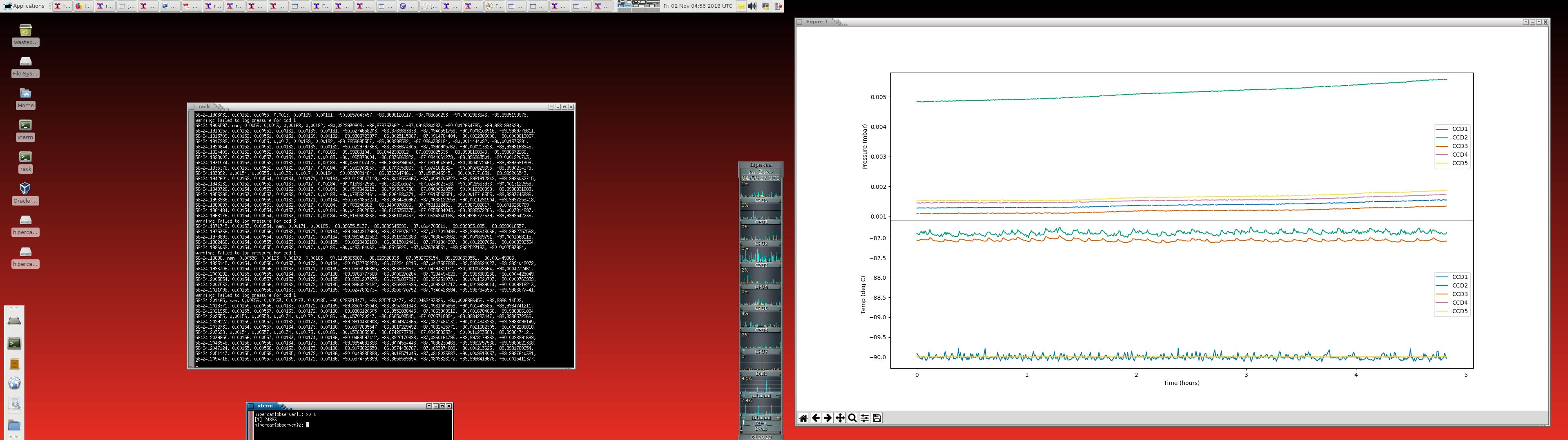
To log the pressures and temperatures during the pumping and cooling procedures, go to the control room and use the DRPC to open a terminal on the rack PC and, in the
/home/insuserdirectory, typehw_monitor &. This will open amatplotlibwindow displaying graphs of the pressures and temperatures of the CCDs as a function of time, starting from when thehw_monitorscript is run. The values are also stored in an ASCII file calledhw_log.txt, also in the/home/insuserdirectory.To view an automatically-updating list of the pressure and temperature values, type
tail -f hw_log.txt. Note thathw_monitorscript always appends to this file, never overwrites it, but only plots the pressures and temperature values obtained since the script was run. At the end of a run at the telescope, move thehw_log.txtfile to/home/insuser/hw_log_oct18.txt, for example, to prevent the file becoming overly large and disjoint. A new file will then automatically be created in the home directory when thehw_monitorscript is next run. To plot old log files, use the python script/home/insuser/old_hw_logs/plot_hw_log.py.The DRPC desktop should look like the screenshot below. It is recommended that you open the above windows in the middle-left virtual desktop of the DRPC.