


|
0.0.0.0.0.0.0.0.1Document Title |
Ultracam System Maintenance Document |
|
Document Number |
|
|
1.0 |
|
|
Date |
0.0.0.0.1
|
|
Document Prepared By: |
David Atkinson |
Signature and Date |
|
|
Document Approved By: |
|
Signature and Date |
|
|
Document Released By: |
David Lunney |
Signature and Date |
|
CHANGE RECORD
|
Issue |
Date |
Section affected |
Change Description |
|
|
|
|
|
|
|
|
|
|
|
|
|
|
|
|
|
|
|
|
|
|
|
|
|
|
|
|
|
|
|
|
|
|
|
|
|
|
|
|
|
|
|
|
|
|
|
|
|
|
APPLICABLE DOCUMENTS
|
Reference |
Document Title |
Document Number |
Issue & Date |
|
|
|
|
|
|
|
|
|
|
|
|
|
|
|
|
|
|
|
|
|
|
|
|
|
TABLE OF CONTENTS
23
1. Introduction
2. Camera Head Design Overview
Ultracam has three camera heads, one for each of the optical arms of the instrument (r’, g’, and u’ bands). All three camera-heads are identical except for the mounting tabs on their lids, which interface each camera to the main body of the instrument. The camera heads were designed to provide a light tight housing for each of Ultracam’s CCD47-20 frame transfer detectors. Furthermore, there was a requirement to achieve a dark current rate of a least 0.1electrons/pixel/second. This was achieved by cooling each detector to -40C with a Thermoelectric Cooler (TEC), which are solid state devices that use the Peltier effect to pump heat. To aid the cooling performance of the TEC the camera heads were designed as vacuum vessels, this effectively eliminates convective heat loading on the TEC resulting in an enhanced thermal performance. Moreover, a vacuum environment ensures that no condensation can form on the active silicon of the detectors.
The base of the camera head forms a water-cooled heat exchanger, which is required to remove the heat pumped (and generated) by the TEC. The inlet and outlet ports have quick release shut-off valves to provide a clean and quick removal of the water hose connections. Other ports on the camera head include: a compact vacuum port/valve; an hermetic electrical connector for the TEC power supply and cold side feedback temperature; an hermetic connector for the CCD detector electronics; and a passive zeolite sorption pump for added protection against the formation of condensation within the camera head. These ports are highlighted in the photograph of the red camera head displayed in Figure 2.1.
Sorption
pump CCD
Cable Port With
Shorting Plug Vacuum
Port Coolant
Port
(quick
release valve)


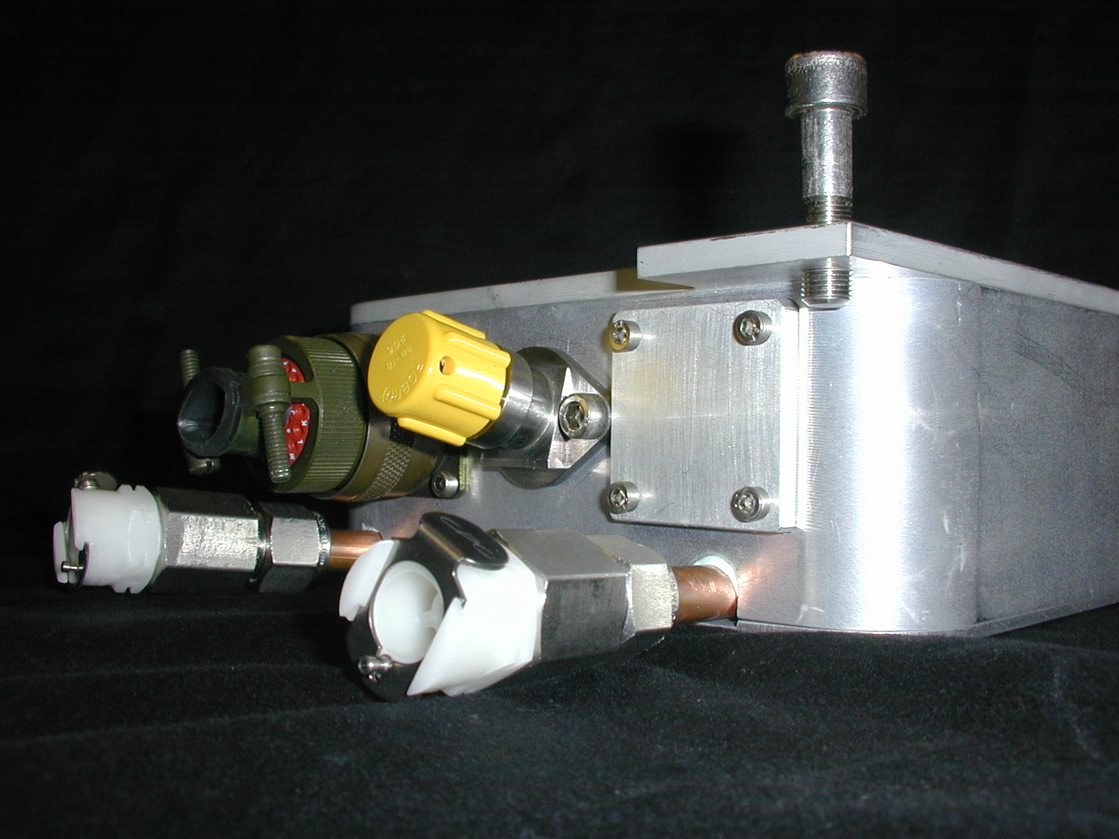
Figure 2.1: Camera Head Ports
3. Pump Down Procedure / Vacuum Maintenance
It is recommended that while in operation the camera heads are pumped down at least once a month. For observing runs less than a month the cameras will only require to be pumped down at the beginning of the run.
As highlighted in Figure 2.1, each camera head has a small vacuum port. A vacuum port operator (shown in Figure 3.1) is provided to open and close the valve and interface the port to standard vacuum parts via a NW10/16 flange. The procedure for pumping down the camera head is as follows.
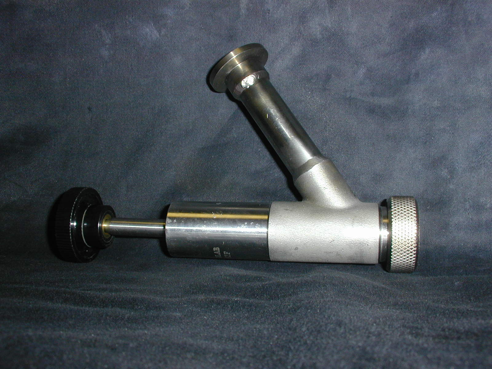
Figure 3.1: Vacuum Port Operator
Procedure 3.1
Connect vacuum port operator to camera head. DO NOT OPEN VALVE
Connect vacuum pump to vacuum port operator.
Switch on Pump
Allow time for pump and interconnecting plumbing to be pumped down to below 1x10⁻³ mbar.
OPEN CAMERA VACUUM VALVE: plunge the dial-shaft home, and turn the dial clockwise until valve fully open. The dial shaft should then be withdrawn to fully open the vacuum port.
Pump down for 3-4 hours (the longer the pump down the better)
CLOSE CAMERA VAUUM VALVE: plunge the dial-shaft home, and turn the dial anti-clockwise until valve fully closed.
Switch off pump.
Disconnect plumbing
Remove vacuum port operator and store in provided plastic cover.
The camera head design includes a zeolite getter (whose location is indicated in Figure 2.1). This is an externally mounted part permitting its removal without the need to take off the camera lid. The getter should be recharged if the camera head is ever opened and exposed to atmosphere. To recharge the getter the following procedure should be followed.
Procedure 3.2
NOTE: This procedure should be carried out in a clean room environment.
Open vacuum valve with a hex key to bring camera vessel to atmosphere.
Remove getter from camera.
Remove o-ring from the getter’s o-ring groove and store in clean environment.
Place getter in a vacuum oven at 200C for 18 hours while continuously pumping down.
Reduced oven temperature to 40C and while continuously pumping let getter cool to this temperature.
Switch off pump and back fill vacuum oven with dry nitrogen.
If vacuum oven in different room from the camera head then transport getter back to the camera head in a sealed plastic bag filled with dry nitrogen.
Attach getter to camera head. Ensure O-ring is back in groove. If the o-ring is dry apply a very thin layer of high vacuum grease to it.
Immediately pump down camera head (see procedure 3.1).
4. ESD Awareness
Electrostatic discharge (ESD) awareness is crucial to protect the detectors from potentially fatal incidents. The internal camera head design includes ESD protection, however, the provided shorting plugs should ALWAYS be connected (as illustrated in Figure 2.1) when the CCD cables (those which connect the cameras to the SDSU controller) are unconnected. Furthermore, these cables should NEVER be connected or disconnected while the SDSU controller is ON. Therefore, the procedure to disconnect the CCD cable from the camera head is as follows:
Procedure 4.1
Switch off the SDSU controller
Put on an ESD wrist strap (which is connected to an earth socket).
Remove the CCD cable.
Insert a shorting plug.
5. System Plumbing
All three cameras and the SDSU controller have a water inlet and outlet to provide cooling. The plumbing connections are all quick-release shut off values to permit quick and clean assembly/disassembly. The units are plumbed together with 10mm insulating clad reinforced hose, which is tied to the instrument struts for safety and neatness. The 3 cameras and the SDSU controller are cooled in series, with the SDSU controller being cooled last. Therefore, the instrument water inlet is the inlet of the GREEN camera, and the instrument outlet is the outlet of the SDSU controller, as illustrated in Figure 5.1. Additionally, there is a compact in-line flow sensor (RS 185-9982) included in the plumbing between the red and blue cameras. This sensor provides an input to service electronics (found in the rack) which only permit mains to be switched through to the TEC power supplies when there is water flow.
Figure 5.1: Ultracam Water Cooling Flow Diagram
The water cooler is a NestlabM-33 recirculation chiller, which can provide 750W of heat sinking at a temperature of 10C. This required temperature is set as follows:
Procedure 5.1
Press the button with the penannular arrow on it.
Alter the set point temperature with the up and down arrow buttons.
Press the button with the penannular arrow on it again to complete altering the set point temperature.
6. Thermoelectric Cooler Controller
The cameras heads utilise a two-stage thermoelectric cooler (TEC) to cool the CCD to under -40C. These devices were purchased from Melcor and the serial number is 2-SC-055-045-127-63. Further information on this product can be found on the Melcor web site: http://www.melcor.com.
Each TEC is powered with an Alpha Omega Instruments (http://www.aoi-corp.net/index.html) Series-800 power supply. The supplies are closed loop PID (Proportional Integral Derivative) controllers, which can supply up to 8A at 15V. The cold-side temperature of the TEC is measured using an AD590 temperature sensor mounted on the ‘coldfinger’, which interfaces the TEC to the CCD. This temperature reading provides feedback for the PID controller, which is configured for this sensor type (see pg. 8.3 of the Alpha Omega Series-800 TEC controller manual). The three supplies are mounted in 19” rack units.
The ‘’ key on the front of the PID controller is known as the ‘home’ key and will always bring the display back to the ‘home’ page. On pressing ‘’ the measured cold side temperature (green) and target or set-point temperature (red) are displayed. The target temperature can be altered by pressing the up and down arrow keys when at the home page. A coldside temperature of a least -40C is recommended for low dark current rates (well under 0.1e/p/s) while not overloading the TEC. When on the home page pressing the circular arrow key will scroll through the following parameters: Temperature, Power Output to TEC (displayed as a % of the full power range), and various PID settings. The power output displays a negative value when the PID Controller is supply cooling power to the TEC, and a positive value when it is supplying heating power. Each PID controller has been configured for use with the ultracam system and PID parameters of P=5.0, I=1.0, D=0.0 have been selected. The maximum power output has been set to +/- 55% to prevent damage to the TEC through over heating. Furthermore, to slow the cooling process, the cooling power output is limited to -20% when the temperature is above -10C. Note that the CCD47-20 should not be cooled or heated at a rate exceeding 5C/min. Details on how to access the various controller parameters can be found in the Series 800 user manual.
WARNING. The Series 800 controller provides an AUTOTUNE function, which on application automatically selects and sets PID parameters to for the attached TEC. However, in doing so the controller scans through its full power range, which exceeds the rated power range of Ultracam's Melcor TECs. Consequently, the autotune function should NEVER be performed with this system. As detailed above, Proportional, Integral, and Derivative values have been selected and a power limit of 55% has been placed on the output of the controller. An AUTOTUNE will override these settings and could damage the TECs.
7. SDSU Controller
7.1. Controller Boards
Ultracam employs a 12 slot Generation II SDSU (San Diego State University) controller to read out the three CCDs in parallel. The controller contains the following boards, all of which are fully described in the SDSU user manual:
One Timing Board: provides digital timing (or sequencing) signals for reading out the CCD, and communicates with the host PC over a duplex fibre optics link.
Three Clock boards: each board translates the digital timing signals from the sequencer to controlled voltage levels for driving each of the three CCD's clock lines.
Three Video boards: each board provides the required CCD bias voltage levels for each of the three CCDs. Moreover, each board amplifies and digitises two video channels from each CCD using a correlated double sampling circuit.
Each clock and video board has a unique address associated with it. This address is established using the four Jumper links JP1 to JP4 as fully described in the SDSU user manual. For ultracam the video and clock boards are addressed as detailed in Table 7.1.
|
BOARD |
ADDRESS |
Inserted Jumpers links (JP1-JP4) |
|
RED camera Video Board |
0 |
JP1, JP2, JP3, JP4 |
|
GREEN camera Video Board |
1 |
JP2, JP3, JP4 |
|
BLUE camera Video Board |
2 |
JP1, JP3, JP4 |
|
RED camera Clock Board |
3 |
JP3, JP4 |
|
GREEN camera Clock Board |
4 |
JP1, JP2, JP4 |
|
BLUE camera Clock Board |
5 |
JP2, JP4 |
Table 7.1: SDSU Board Addressing
7.2. Controller Digital and Analogue Grounds
The controller has separate digital and analogue grounds. These can be connected via jumper link JP9 on any video board. For Ultracam the grounds are connected via JP9 on video board 1.
7.3. Modifications to Video boards
A few minor modifications to the video boards were required to obtain the correct bias levels for the CCD47-20. These are as follows:
Resistor R147 removed.
Resistor R149 removed.
Resistor R128 changed from 2k to 3.9k.
8. Camera Cables, Wiring and Grounding
8.1 Camera Cables.
Each camera head has a cable connecting it to the SDSU controller. The cable plugs into the camera head via the 32-pin circular hermetic CCD cable port illustrated in Figure 2.1. Each of these cables provides the various CCD clock and bias levels to the camera head and returns two channels of video data. Each cable is in fact a composite cable containing four separately shielded cables: one for the clock signals; one for the bias signals; and two single-core co-axial cables for each of the video channels. At the SDSU end of the cable, the 37-pin D-Type connector plugs into the associated clock board and the 25-pin D-Type connector plugs into the associated video board. The two co-axial cables (carrying the left and right channel video signals from the CCD) connect to the two SMA sockets J2, and J4 on the video board, whose locations are indicated in Figure 8.1. For the blue and green cameras the right video channel is routed to the SMA connector J4, and the left video channel to SMA connector J2. Conversely, for the Red camera these channels are reversed with the left video channel to J4, and right video channel to J2. These connections are summarised in Table 8.1 below.
|
Camera |
Red |
Red |
Green & Blue |
Green & Blue |
|
Video Channel |
Right |
Left |
Right |
Left |
|
Video Board Connector |
J2 |
J4 |
J4 |
J2 |
Table 8.1: Video channel connections to SDSU Video Board
The blue and green camera cables are identical. However, the red cable has some differences. Firstly, it is 200mm shorter than the other two since it is closer to the SDSU controller. Moreover, since the image taken with the red camera is a mirror image of that taken with the blue and green cameras some of the clock signals are routed differently. Specifically, the readout register clock signals: RL, R1L, R2L, R3L, RR, R1R, R2R, and R3R. The cable wiring schedules are provided in Figures 8.2(Green and Blue camera), and Figure 8.3(Red camera).
Figure 8.1: SDSU Video Board Connectors
8.2. Camera Wiring
Inside each camera, the CCD is mounted on a small PCB which routes all the various clock, bias, and video signals to and from it. Signals are routed from the hermetic cable plug to the PCB via PTFE insulated copper wire, and interface with the PCB using two 'microD' connectors, one for the clock signals, and one for the video and bias signals. The wiring schedule is provided in Figure 8.4.
8.3. Detector PCB
Each CCD is mounted on a detector PCB, which routes all the clock, bias and video signals to and from it. In addition, the detector board design provides ESD protection for the CCD using the SP720 chip, and has the capability (although not included in the delivered system) to provide a video gain stage. The complete design is detailed in Figure 8.5, however, the following modifications (i.e. removal of gain stage) have been made to the delivered boards.
Linked J3 pin 34 to J2 pin 7 (Dump gate signal which comes in on clock side but was originally routed from bias side)
Removed resistors: R1, R2, R4,R5,R7,R8, R9 ( and link across R9 pads), R11, R12, R14, R15, R16 (and link across R16 pads)
Removed capacitors: C19, C20, C21, C22, C24, C25,`C26, C28, C29, C30, C98, C99
Remove components U1, U2, Q1 and Q2.
Link U1 pin 3 to pin 6, U2 pin 3 to pin 6, J6 pin 1 to pin 2, and J7 pins 1 to pin 2.
Figure
8.2 Blue and Green Camera Cable Wiring Schedule
Figure
8.3 Red Camera Cable Wiring Schedule
Figure 8.4 Internal Camera Wiring Schedule
Figure 8.5(a): Ultracam Detector PCB
Figure 8.5(b): Ultracam Detector PCB, left channel gain stage (not included in delivered system)
Figure 8.5(c): Ultracam Detector PCB, right channel gain stage (not included in delivered system)
8.4: Bias and Clock Voltage levels
Figures 8.2 and 8.3 detailed the wiring of the various clock and bias signals from the SDSU controller to the camera heads. Table 8.2 presents the voltage levels of these signals.
|
SIGNAL NAME |
SIGNAL LEVEL (Volts) |
|
|
Bias Voltages |
|
|
|
ODL |
20.5 |
|
|
ODR |
20.5 |
|
|
ABD |
20.5 |
|
|
RDL |
8.5 |
|
|
RDR |
8.5 |
|
|
OG |
-5.5 |
|
|
ABG |
-8.0 |
|
|
Clock Voltages (Blue/Green) |
HI |
LO |
|
RL, RR |
2.5 |
-8.5 |
|
R1R,R2R,R3R |
0.5 |
-8.5 |
|
R1L,R2L,R3L |
0.5 |
-8.5 |
|
DG |
2.5 |
-9.5 |
|
I1,I2,I3 |
2.5 |
-9.5 |
|
S1,S2,S3 |
2.5 |
-9.5 |
|
Clock Voltages (Red) |
HI |
LO |
|
RL, RR |
1.5 |
-9.5 |
|
R1R,R2R,R3R |
0.0 |
-9.0 |
|
R1L,R2L,R3L |
1.5 |
-9.0 |
|
DG |
1.5 |
-10.5 |
|
I1,I2,I3 |
1.5 |
-10.5 |
|
S1,S2,S3 |
1.5 |
-10.5 |
Table 8.2: CCD Clock and Bias Voltage Levels
9. Instrument Rack
The electronics rack contains the five 19” units described below.
TEC Protection Electronics and GPS box.
The top shelf has a small box mounted on it, which contains service electronics for the TEC power supplies. This ensures that the power supplies to the TECs can only ever be on when there is water flow in the coolant pipes. There are two inputs to this unit, the flow sensor cable which comes from the instrument itself, and a 9V power supply. There are also 3 BNC output connectors, which are cabled to the connectors labelled 'Power Control' on the racks containing the TEC power supplies. The circuit diagram schematic for this unit is provided in Figure 9.1. This shelf also houses the GPS receiver box.
Rack Unit Housing 2 TEC Power Supplies
The second unit houses two Alpha-Omega Series 800 PID controllers. At the back of this unit two connections can be found for each of these supplies. Firstly, a six-pin circular Peltier power supply socket, to which a 5m Peltier power cable is attached to go to one of the camera heads. Secondly, a BNC socket to connect a co-axial cable to the TEC protection electronics described above.
Rack Unit Housing 1 TEC Power Supply and 1 SDSU Power Supply
This third unit houses another Peltier power supply (with similar connections at the back), and the SDSU power supply unit (PSU). A separate power ON/OFF rocker switch is provided for the SDSU PSU.
PC
The forth unit is the rack mountable PC running Linux. The following connections are required to the PC.
GPS Cable, which connects the serial port of the PC to the GPS box mounted on the top rack shelf.
Timestamp Cable, which connects the parallel port of the PC to the front panel of the SDSU controller.
Duplex fibre optic link, which connects the SDSU PCI interface card to the back panel of the SDSU controller. Note that if the green LED on the PCI interface board is not on when the SDSU controller is on, then the fibres are connected to the wrong ports and require to be swapped.
Raid array cables, which connect the raid card in the PC to Raid Array rack unit. Details of the raid array cabling are shown in Figure 9.2.
RAID ARRAY
The fifth and final unit is the raid array itself
Figure 9.1: Ultracam Flow Sensor Circuit
Figure 9.2: Raid Array Cabling
.
![]()