These instructions tell you how to mount ULTRACAM on the NTT. They were written following an installation on 6th January 2011.
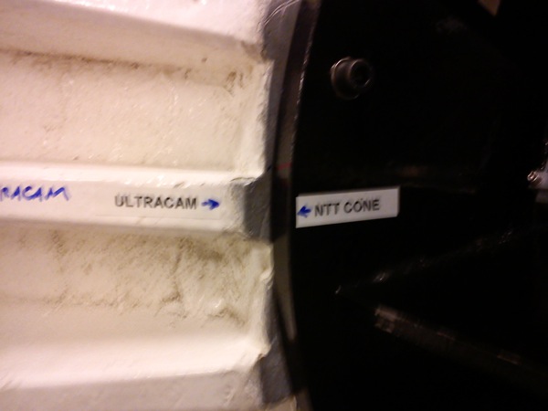
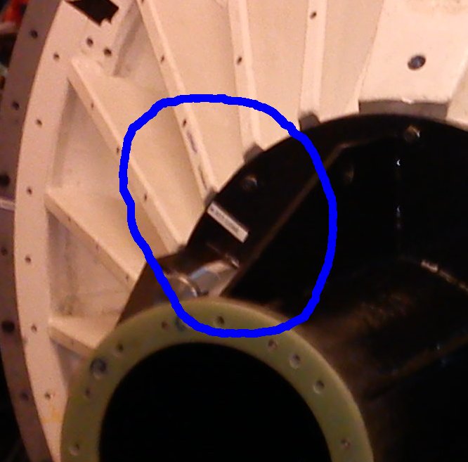
The days installation work went as follows - on site technical staff spent until 11am removing the previous instrument and mounting the NTT to ultracam adaptor collar (a huge white casting) on the rotator. Before starting, check that the technicians have correctly lined up the ultracam adaptor collor to the rotator flange. Labels on both parts should be lined up as shown.
At 11am (actually we were 20 minutes late) we show up and ultracam hardware is mounted on the collar. Between about 12:00 and 1:30 we cabled up ultracam. After lunch, the technical staff balanced the rotator for the new loading of ultracam plus its cabling. Finally, we turned on and tested the cooling and data acquisition subsystems, adjusted the cabling to minimize CCD noise, and went to the control room to check connection via ETHERNET.
A word from those more experienced than me in installing and deinstalling ULTRACAM - be very careful to be neat and tidy in getting out and putting away the parts! Anything that goes missing, even one bolt, can really make installation very hard. Especially during deassembly, be very careful to put everything back in the correct bag, and the bags back in the correct boxes. The packing lists should still be correct when we are ready to ship back to Sheffield or off to the next instrument. Also, cable assemblies are delicate. Do not throw, drop, or jerk cable connectors as this can cause unseen damage that can then be very hard to diagnose, wasting valuable time later.
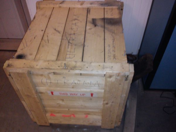
There are six shipping cases. Each box has a packing list taped to the inside of the lid. Crates 1, 2 and 6 always hold the same items. Crates 3, 4 and 5 have contents that may vary. You will need to examine the packing lists and find the different components. The ULTRACAM packing cases consist of five flight cases and one wooden crate. The flight cases are all clearly marked ultracam; the wooden crate has ULTRACAM written on it roughly in marker pen. Below are pictures of a typical flight case and the wooden crate.
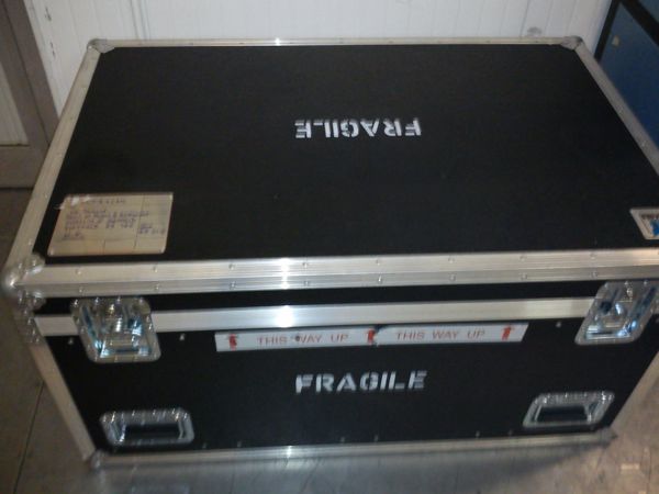
Crate 1 is a flight case containing the electronics rack.
Crate 2 is a flight case containing the ULTRACAM canera
Crates 3 and 4 are flight cases containing small spare parts and tools
Crate 5 is a flight case containing large spare parts.
Crate 6 is a wooden crate containing the ULTRACAM mounting plate.
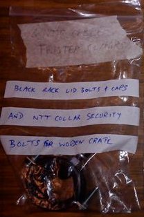
This mounting bracket is in the wooden crate. The mounting bracket is black painted steel. Remove the security bolts clamping it into the wooden box and place them in the bag of bolts pictured below, to be found in the ultracam bolts cardboard box.
Crane using the metal lifting eye that should be in the crate with the bracket. See figure below.
It is important that the rotator is adjusted until the arrow on the white ULTRACAM mounting plate lines up with the corresponding arrow on the mounting bracket. See figures below.
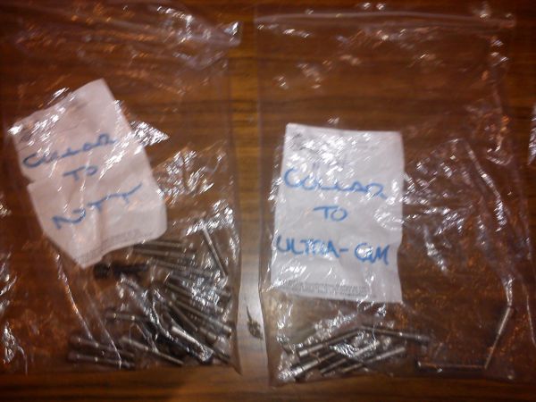
In one packing cases 3 or 4 (it was 4 for us) there is a cardboard box labeled Ultracam Bolts, containing numerous plastic bags of bolts for various purposes. Find this box and get the bag labelled COLLAR TO NTT, shown in the figure below.
Use these bolts to fix the bracket to the telescope. Excess bolts should be kept in the bag, and the bag replaced in the box of Ultracam Bolts.
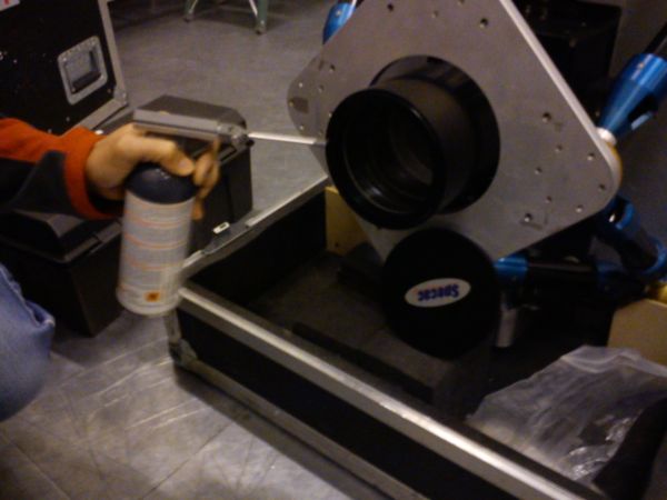
Crate 2 has a deep lid and a shallow base. The lid is removed upwards leaving the detector mostly exposed. The input port is covered by an anodized aluminium plate held on with tape. This lid should be removed temporarily and the input optic sprayed lightly with air cleaner as shown in the figure. Spray cleaner should be used with care. First shake can. Always hold the can upright when spraying. Spray into air first in case there is some initial contamination in the nozzle or bottle. Once air stream is clean, spray the lens surface lightly, again holding the can upright.
The plate should then be masking taped back into place. Do not use GAFFER/DUCT/DUCK tape on ULTRACAM parts as it leaves sticky residue.
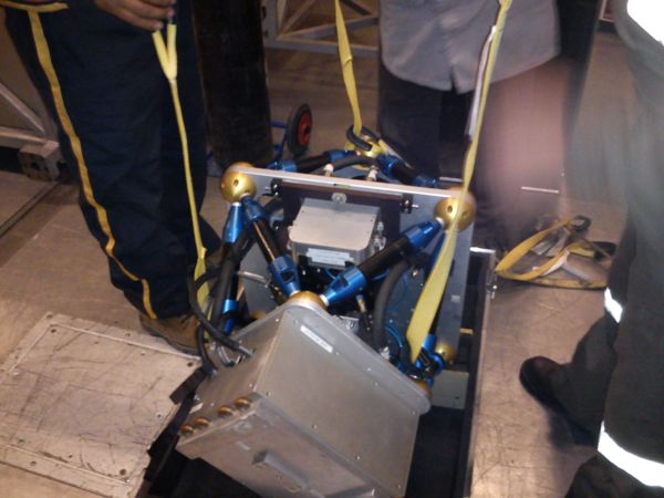
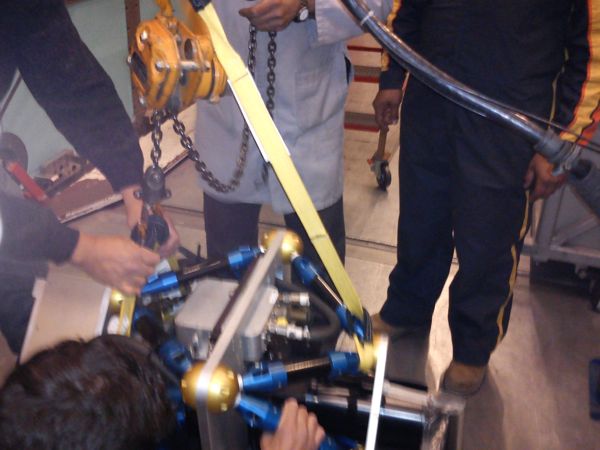
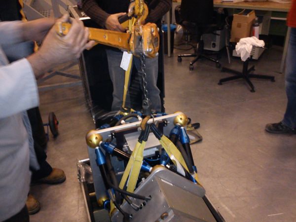
Craning is via three lifting straps looped under the carbon fibre
struts as shown in the picture below. Care should be taken to go under
the downward pointing struts so that the loop cannot slip when the
load is lifted. Note also that two of the straps when looped under are
much shorter than the third; these were both attached to a chain hoist
which was used to equalize the length of the three suspensions from the
crane hook, so that ULTRACAM hangs with the mounting plate vertical.
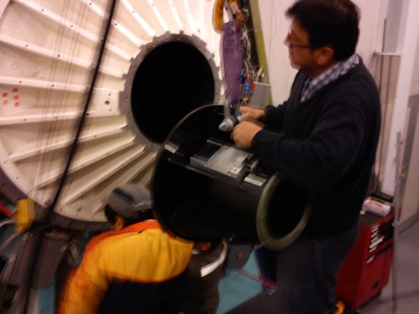
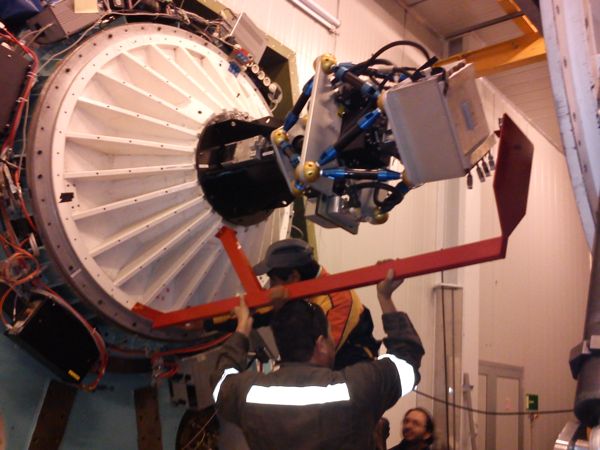
Hoist ULTRACAM so that its mounting plate is in close proximity to the black mounting bracket. Just prior to mounting, the anodized aluminium disc covering the input port is removed.
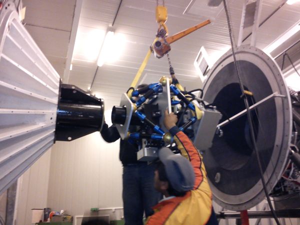
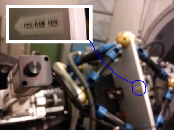
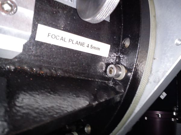
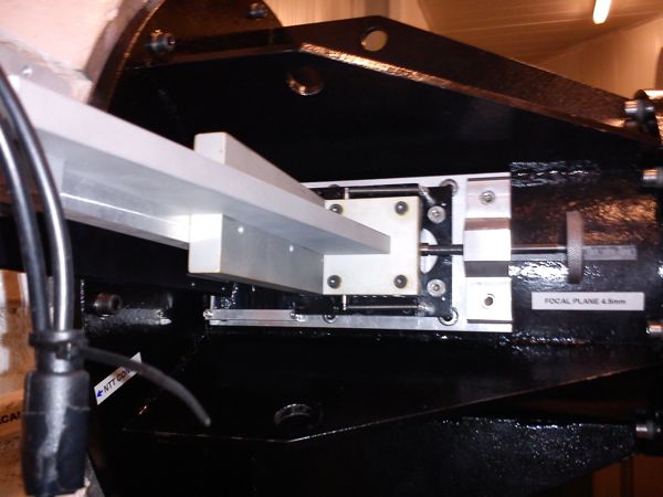
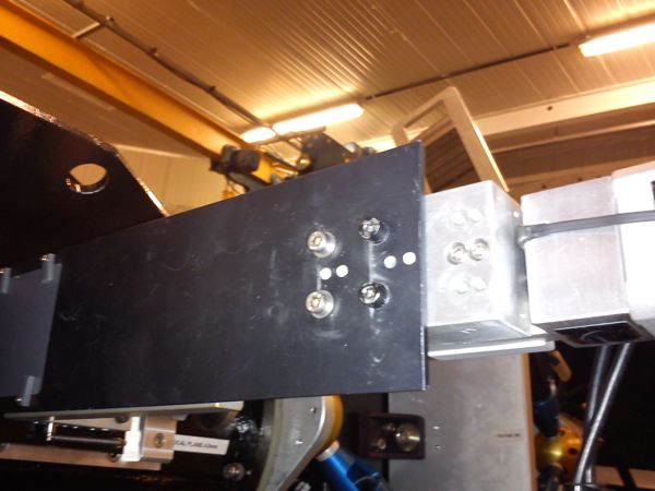
The rotator should be adjusted so that ULTRACAM and the mounting bracket have aligned labels as shown in these figures before they are bolted together. Note the label that indicates correct alignment of ultracam to the mounting plate on the upper figure. If this label is obscured, note from the second figure that a sticker labelled focal plane mask should line up with the focal plane mask fixture. Only the mounting plate for the focal plane mask and the screw vernier adjuster will be present at this stage.
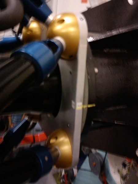
The bolt packet labelled COLLAR TO ULTRA-CAM shown in an earlier figure next to the bag of bolts to connect the collar contains bolts for attaching ULTRACAM to the mounting bracket, and also insulating bushings for electrical isolation of ULTRACAM from the telescope ground. It is important that these bushings and bolts are used, and not some other bolts with no bushings. See the detail below.
Do not tighten the bolts too hard into the aluminium body of ULTRACAM or you risk sheering off the threads. Once the bolts are fairly tight, but not over-tight, use the rotator to turn the assembly upside-down, then tighten the bolts again, particularly those which are on the bottom after rotation. Once all bolts are tight, rotate ULTRACAM back to the original position.
The figure below shows the cable rotator fixture being attached. The technical staff have suitable bolts for this piece. It doesn't actually matter in what orientation the cable rotator is mounted, though it seems sensible to have it at the bottom when ultracam is upright.
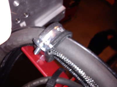
The bag of bolts pictured below contains the cable retainers to be attached to the cable rotator flange at the top end of the rotator. Theses should be put in place loosely in preparation for cable laying.
At this point, the technical staff have no further role until the cabling is finished.
The focal plane mask mount is shown in the figure below, along with the two packets of bolts needed for the assembly. The mounting bolts are used to attach the mount to ULTRACAM as shown in the third and fourth figures below. Notice the four non-anodized countersunk bolts used to attach the mounting plate to the side of ULTRACAM. These bolts are in the bag labelled FOCAL PLANE MOUNTING BOLTS.
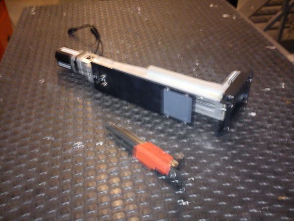
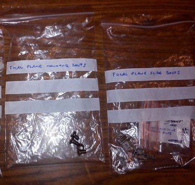
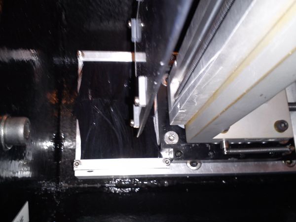
Next, the actual focal plane mask is attached to the side of the mount by pulling back the slide assembly slightly and attaching using the four bolts from the bag labelled FOCAL PLANE SLIDE BOLTS.
Water cooling hoses run from the chiller cold output, in to the green CCD input. The other long water cooling hose returns to the chiller warm input from the outlet port on the SCSU box. Between the input and the output, short hoses connect water cooling in the order green, red, flow sensor, blue, SCSU box. Normally these hoses should already be connected, but check that this is so before using the cooling. Note that the SCSU box has two cooling tubes, and that the output of one is connected to the input of the other with a short flexible hose, so that therefore the SCSU box has four ports for water hoses. The flow sensor turns off the peltier coolers if water ceases to circulate via a control box in the electronics rack.
The electrical cable harness should be coiled using removeable cable ties. These should be removed and the cables attached at the ULTRACAM end first. The first connection to make is the multi-pin AMPHENOL (military) SDSU power cable. Next, also connect the three AMPHENOL peltier cooling cables, one to each CCD housing. Next, connect the GPS interrupt cable (A BNC cable) to the BNC 'T' on the SDSU housing. Next, connect the flow control cable, which is a screw thread locked 3 pin cable of obscure type. It's shiny. Next, connect the focal plane slide cable, which is multi-pin miniature DIN type. Next, connect the fibres, being careful with the exposed surfaces. All cables should be carefully fed so as not to touch each other unduly. From ULTRACAM all cables should pass through the two rotator brackets such that they are not tangled or twisted. Take some care over this. Removable cable ties should be used to secure the cables strain relieving the electrical connections as appropriate. Removable cable ties should be re-attached to the cable bunch so that the cables all run back into the cone of the rolled-back detector as shown in the figure below.
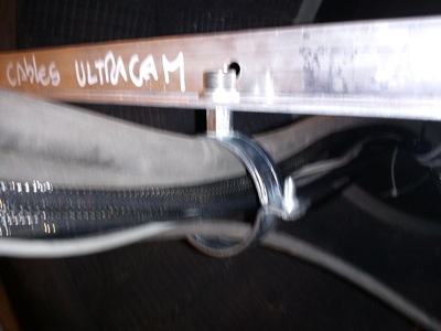
This is an image of the metal plate used to ensure that a metre of straight cable is available to take up the rotation between the ULTRACAM output and the next clamping point.
This is a picture of the support bar used to mount the cable rotator clamp on the removed laboratory detector.

The water chiller hoses should now be inserted into the cable rotator brackets, again ensuring that there is no tangling of the cables. The electical cables, fibres, water chiller cables, and nitrogen gas line should all now pass through the cable rotator and loop back inside the cone of the removed detector before dropping vertically to the metal support frame of the removed detector. Inside the cone of the removed detector, a small metal plate is attached and used to mount a chain of cable ties that holds the cable loop horizontal for approximately a metre from the point where it leaves the ultracam electronics.

This metre of cable is sufficient for rotation of the detector. Once the cable loom drops to the metal frame, cable ties are used to route the electrical/fibre, nitrogen, and water lines towards the the rack, chiller, and gas bottle respectively. Neatness is important to avoid making mistakes, damage, tripping, and to ensure any debugging that proves necessary during observing is as efficient as possible.
Finally, it may be that the techical staff wish to run cables in our loom to the rotator. During our installation on 2011/01/06, a mains cable to power the rotator electronics was routed this way. After all cables are in the loom, the cable rotator brackets are tightened using the two retaining bolts of either side of each of the two brackets. The cable looms should be loose inside these brackets to allow free rotation of the cables when the rotator is operated. The figure below shows the final configuration of ULTRACAM and its cables.

The mains connector used to power the electronics rack and the chiller is an orange reel below and to the right of the rotator flange. See the figure below. The longer of the two mulitway extension cables having a German-type plug and a 4 way UK mains distribution board is connected to this outlet, and the cable is run along the transport rail for the lab detector, then the distribution board is cable tied to the support frame for this detector. Further mains connections to the rack and the chiller will be made from there. Striped safety tape is used to tape the mains cable to the floor to minimize the risk of tripping or damage.

From this connector, the chiller, positioned at the back of the room adjacent to the air conditioner unit behind the steel frame, is connected to the mains. Check at this stage that the chilled water is filled to the indicator line. Connect the send and return hoses at the chiller end by pushing them on. Ensure that the cold send line is connected to the green CCD input, and the hot return line is connected from the SDSU box.
The electronics rack is positioned adjacent to the steel support frame for the removed laboratory detector on which the mains distribution board was cable tied. Ensure that everything in the rack is off - both the computers, the peltier cooler control units, the GPS controller, before connecting the mains plug for the rack to the distribution board. Check again that nothing has come on.
Refer to the user manual from Vik for further instructions.