ULTRACAM user manual
Vik Dhillon, version: 27 February 2026
- Introduction
- Powering up
- Powering down
- Afternoon activities
- Software startup
- Looking at data
- Logging of data
- Observing
- Archiving data
- Drift mode
- Changing filters
- Before you go to bed
- Troubleshooting
- Contacts
Introduction
This manual describes how to observe with ULTRACAM. Other useful
information can be found in:
- ULTRACAM
MNRAS paper. This paper summarises the design and performance of
ULTRACAM. Local copy available here.
- CCD
application document. This document describes the various CCD
controller applications that can be run with ULTRACAM in more detail
than the above paper. You should regard the applications document,
which is written by David Atkinson (UKATC), as the primary source of
reference for the different readout modes and their associated
parameters.
- ULTRACAM
system maintenance document. This document describes ULTRACAM's
camera head handling and system maintenance procedures. Written by
Dave Atkinson (UKATC), it should only be of relevance to project
personnel.
- HiPERCAM pipeline
software manual. This document describes how to use Tom
Marsh's HiPERCAM pipeline data reduction software, which
superseded the old c-based
ULTRACAM pipeline and is now the recommended
way of viewing ULTRACAM data whilst observing.
- ufinder. This
is Stu Littlefair's observation planning and finding chart tool
for ULTRACAM.
- UCam
User Manual. This is Stewart McLay's user manual for the UKATC
UCam data acquisition system, which is used by ULTRACAM. Useful
information can also be found in the corresponding UCam
Installation Manual and the UCam
Configuration File Reference Manual.
- GPS170PEX
User Manual. This document contains the Technical Information
and Operating Instructions for the Meinberg GPS170PEX, the latest
ULTRACAM GPS system installed in March 2010.
-
ULTRACAM logistics page. Details the status of ULTRACAM computers, system
backups and data archiving.
-
Telescope operators guide. This document describes how to use
ULTRACAM with the WHT Telescope Control System and is intended
primarily for telescope operators at the ING. There is a
corresponding web page for the telescope operators at the NTT, but
I'm not sure of the link to it.
- Paul Kerry's user guide to the ULTRACAM computers. This can be
found by typing evince
/home/star/ultracam_userguide/ultracam_user_guide.pdf on the
data reduction PC, and a paper copy resides in the blue ULTRACAM
folder in the black ULTRACAM crates at the NTT. I don't provide a
link to it here as it contains all of the system passwords - please
do not distribute or email the above document.
- The ULTRACAM google site. Only team members can access this, and
it contains various useful links, e.g. to the Phase II pages, La Silla
weather, observing blogs, observing checklists and tips, and remote
connection details.
- Ed Daw's ULTRACAM+NTT installation manual. This is now redundant given that ULTRACAM was
successfully commissioned on the NTT cube in September 2019.
- Liam Hardy's ULTRACAM+WHT installation manual.
- Silvia Catalan's ULTRACAM+WHT installation notes.
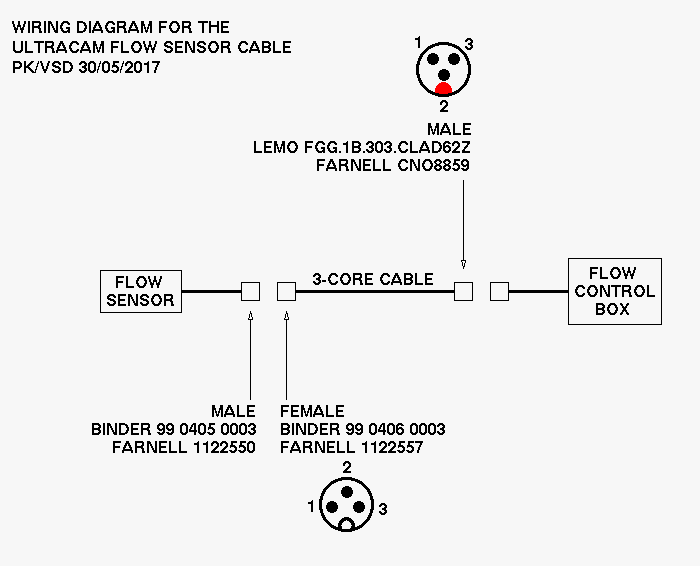
- Wiring diagram for flow sensor cable: .fig, .png.
Powering up
For a short summary of the instructions below, please refer to
this document.
A description of how ULTRACAM's cables and pipes are connected is
outside the scope of this manual, and it will be assumed that this
procedure has already been successfully accomplished. Since September
2019, ULTRACAM has been mounted on the NTT cube and users no longer
need to mount/dismount the instrument at the start/end of each
run. For details of how it used to be done on the NTT, please refer to
Ed Daw's
ULTRACAM+NTT
installation manual. For details of how to do this on the WHT,
please refer to Liam Hardy's
ULTRACAM+WHT installation
manual. To then start ULTRACAM from cold, the following
operations must be performed:
- In the control room, check that the ULTRACAM network switch
housed in the blue NETGEAR box near the data reduction PC is powered
on.
- Turn on the data reduction PC, which is located behind the ULTRACAM
monitor in the control room.
- In the dome, check that the green illuminated switch on the
mains socket strip at the top of the rear of the electronics rack is
lit - this means that the rack is connected to the
mains. Note that it may be difficult to see the green light as it is
usually covered in black tape to prevent light pollution in the
dome.
- When the mains socket strip switch is turned on, the rack PC
should start booting up automatically - you can tell this is
happening due to the loud fans that start up. The rack PC is
located in the bottom of the electronics rack and runs the
ULTRACAM data acquisition system. If the rack PC doesn't start up
automatically, it is likely that the remote power module (RPM) has
been switched off. The RPM is the black box on the second shelf
down in the electronics rack, to which the rack PC power is
connected. To turn on the RPM, flick the red switch at its rear
(which again may be covered with black tape), and the rack PC
should then start booting up. The imedia PC, located just below
the second shelf in the rack and which is used to monitor the
peltier temperatures and control the focal-plane slide, should
also boot up automatically. Note that it is very easy to dislodge
the power cables going into the rear of the RPM when turning it
on, so ensure that they are securely pushed in.
- If you want to see what is happening on the PC whilst it is
booting, use the sliding LCD monitor and keyboard at the top of the
rack; turn the silver knob clockwise to release the lid, slide out
(it can be stiff!) and press the top-most button on the left-hand
side of the monitor to power it on. To switch between the rack and
imedia PCs, click the green button mounted on the front of the small
grey box (D-Link KVM switch) on the shelf in the rack PC. Remember
to turn the monitor off again when finished. To stow away, release
the two catches at the front left and right-hand sides
simultaneously and push in.
- Turn on the SDSU controller by flicking the switch "SDSU POWER
SUPPLY" from 0 to 1. The switch can be found approximately half way
up the rear of the rack near the centre of a white panel. If
successful, two green LED's should illuminate on the SDSU controller
itself, which is located on the base of the instrument - the LEDs
are hidden behind a black velcro strip. There should be no lit LEDs
on the SDSU-PCI card in the rack PC. (Need to
check this). If nothing happens, make sure the switch on the
mains input connector to the Peltier/SDSU power supply unit is also
switched from 0 to 1. If this doesn't work, check the fuses (see
the Troubleshooting section for
details).
- Don't flick any of the switches described below
until you have read the whole of items 8 to 12. It is
possible to damage both the peltiers (if there is no water flow) and
the chips (if they are cooled too quickly) if the following
procedure is not followed.
- Make sure that the power to the
peltier temperature controllers is switched off. The peltier
temperature controllers are located in the two aluminium-fronted
units of the electronics rack. To turn off the power to peltier 3,
flick the switch marked "PELTIER 3" at the rear of the rack from 1
to 0. To turn off the power to peltiers 1 and 2, locate the label
"PELTIER 2" at the rear of the rack and then flick the switch to the
right of this (next to where the mains cable plugs in) from 1 to 0.
- Ensure that the reservoir of the water chiller has been filled
with bottled water to its maximum mark. Now turn on the water
chiller by flicking the switch at the top of the rear of the unit
and then pressing the right-hand button on the front panel with the
"I/O" on it. The chiller will spring into life and you
should immediately check both that the peltier temperature
displays at the front of the rack remain unilluminated and that none
of the pipe connections on the chiller, SDSU controller, flow sensor
(attached to the underside of the mid-plate of ULTRACAM) are
leaking. If you discover a leak, or if the peltier temperature
displays illuminate, immediately power the water chiller off. If you
have a leak, try disconnecting and reconnecting the pipe, and/or
changing the bend of the pipe, and/or rotating the pipe until the
leak stops. If this fails, check the o-rings for damage and, if
necessary, replace the connector using the box of spares in the
crates.
- The current temperature of the water is displayed on the
front panel of the chiller and it will begin to drop as the chiller
starts cooling the water down to the set temperature. The set
temperature should be 10 degrees, unless this is within
approximately 5 degrees of the dew point (in which case the water
temperature should be increased). The dew point can be determined
from the observatory's meteorological system. A useful check on this
is to run your hand along the base of the SDSU controller - if it
feels even slightly clammy to the touch, increase the set
temperature. To change the set temperature, press the left-hand
button with the penannular arrow on it and then alter the set
temperature with the up and down arrow buttons. Press the button
with the penannular arrow on it again to complete the setting
process.
- After the chiller has been running for a short while, you may
notice that the water level has dropped compared to when you turned
the chiller on. This is most probably because of air pockets in the
plumbing. It is important that you top up the reservoir in this
case.
- Turn on the peltier temperature controllers, which are located
in the top two units of the electronics rack. To turn on the power
to peltier 3, flick the switch marked "PELTIER 3" at the rear of the
rack from 0 to 1. To turn on the power to peltiers 1 and 2, locate
the label "PELTIER 2" at the rear of the rack and then flick the
switch to the right of this (next to where the mains cable plugs in)
from 0 to 1. The peltier displays on the front of the rack will now
illuminate. If nothing happens, make sure the switch on the mains
input connector to the Peltier power supply units are also switched
from 0 to 1. If you get an "Err" reported, which typically happens
with the green peltier controller when using the longer 7.5m cable
at the NTT, see the Troubleshooting
section for how to recover.
There is one display for each CCD head. The upper
figure on the display shows the current CCD temperature and the
lower figure shows the set temperature. The temperature controllers
will immediately begin cooling the chips to the set temperature by
running the peltiers at their maximum power of -55%. However, it is
possible to damage the peltiers by allowing them to cool by more
than 5 degrees per minute, so it is essential to
immediately increase the set point to 5 degrees below the
current chip temperatures using the up and down arrow buttons to the
right of the temperature displays. Once attained, drop the set
temperatures by approximately 5 degrees per minute until the desired
temperature of -40 degrees is reached. Once the chip temperatures
have stabilised at -40 degrees, check the peltier power levels by
pressing the left-hand turquoise buttons on the temperature displays
once. The power level should be approximately -30% to -35%. If the value is
close to or equal to the maximum value of -55% then the heads may
have lost their vacuum and need to be pumped down. Alternatively,
the water chiller might be running at too high a temperature. You
can return to the temperature display by pressing the black button
in the middle.
As of March 2022, the above cool-down procedure is now obselete, as
Peter Sinclaire (ESO) implemented the ramp function in the peltier
controllers. This automatically cools (and warms) the CCDs at the
safe rate of 5 degrees per minute. So you can simply set the temperature
to the required value and leave the controller to cool/warm to
the set temperature. I'm going to leave the old procedure described
above in the user manual though, just for information.
- Ensuring that the focal-plane slide is in the
home position, slide the M4 mirror into the beam. If
you've never done this before, please ask Vik Dhillon for
instructions.
Powering down
For a short summary of the instructions below, please refer to
this document.
During an observing run it is normal to leave the SDSU controller,
water chiller and peltier coolers running continuously to prevent
unecessary thermally and power cycling. It is no longer necessary to
dismount ULTRACAM at the end of each observing run, as it is now
permanently mounted on the NTT cube. If there are relative short gaps
between observing runs (of up to a week or two), we recommend
leaving the instrument running. For longer gaps, the instrument should
be powered down at the end of the run, in the following order
(refer to the Powering up section for the
location of all relevant switches and devices).
- In the control room, prior to shutting down
udriver on the data reduction PC for the last time, home
the focal-plane slide. This is absolutely essential, as otherwise
anyone sliding the M4 mirror out of the beam will collide it with the
blade, likely destroying it and showering the ULTRACAM collimator with
bits of metal!
- Still in the control room, ensure that
the end_of_night_tasks has successfully completed on the
data reduction PC.
- Now go up to the dome, and turn off the SDSU controller.
- Then turn off the water chiller. This will cut the water flow and hence
will automatically turn the peltiers off (but check the peltier displays
to make sure). With all cooling turned off, the chips will gradually
warm up to ambient temperature at a safe rate.
- Turn off the peltier temperature controllers.
- If you've forgotten to home the slide, you've got
one last chance - you can move it by logging into
the imedia PC and following the instructions given in
the Drift mode section.
- Shut down the rack PC by logging in as root and typing "init 0" in
an xterminal connected to the PC or by using the sliding monitor and
keyboard in the electronics rack (if doing the latter, make sure the
KVM switch - the grey D-Link box on the rack shelf - is set to the
rack pc login window rather than the imedia login window). This does
not turn the PC power off, so when the LCD monitor says the system is
halted you can press the power button on the front-panel of the rack
PC.
- Shut down the imedia PC by pressing the toggle switch on the front
of the unit - the unit will automatically power down after approximately
30 seconds.
- Turn off power to the entire ULTRACAM electronics rack by
switching off the green illuminated switch on the mains socket strip
at the top of the rear of the electronics rack.
- If instructed to do so by Paul Kerry or Vik Dhillon, shut down the
data reduction PC in the control room by selecting the Log
Out option from the Applications menu on the bottom bar
and then select Shut Down. Then turn off the network switch, data
reduction PC speakers and monitor. If Paul or Vik say
nothing, please leave the DRPC and peripherals
running, and just log out of the window manager.
ESO asked me for a simple one-page
summary of the above shutdown procedure which is printed out and
attached to the front of the ULTRACAM electronics cabinet for easy
reference.
Afternoon activities
Before you start observing in the evening, you should perform the
following system checks.
In the dome
If you are observing remotely, you will be unable to perform most of
the checks below, apart from items 4, 10 and 11. Please assume that
the day-time ESO staff will attend to the other items.
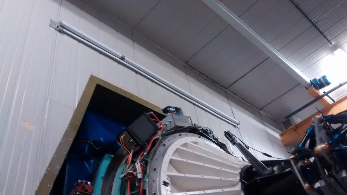
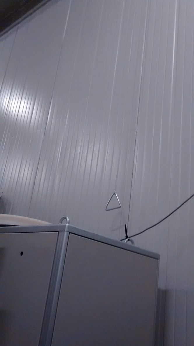
- If there is heavy rain, it is likely that water will leak
through the roof of the NTT Nasmyth room. To protect ULTRACAM from
drips, there is a roll-away plastic cover above the rotator (see
photo) which normally covers EFOSC. This has
two carabiners attached to it, which must be clipped to the
triangle-shaped fastenings on the far wall
(see photo) in order to hold the screen in
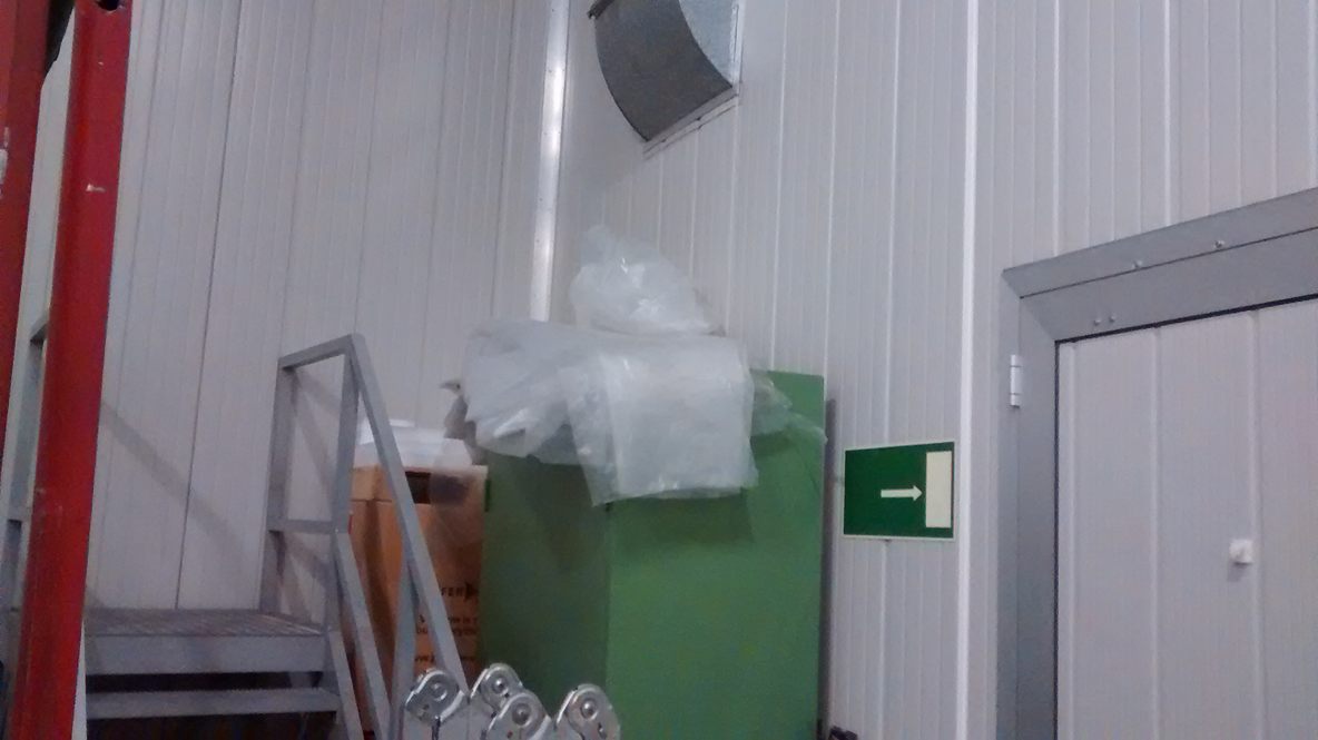
place over ULTRACAM. If necessary, you should ask ESO for an
additional piece of plastic (usually stored on top of the green
cupboard in the Nasmyth room - see photo) to
cover any bits of the instrument that may stick out.
- Check water temperature on the chiller display is set to 10
degrees unless this is within approximately 5 degrees of the dew
point (in which case the water temperature should be increased). The
dew point can be determined from the observatory's meteorological
system. A useful check on this is to run your hand along the base of
the SDSU controller. If it feels even slightly clammy to the touch,
increase the water temperature slightly.
- Check the temperature of the air in the Nasmyth room. The water
in the chiller reservoir will freeze if the ambient temperature
approaches 0 degrees. This is because the fan in the chiller blows
air past the reservoir on its way to the heat exchanger. Hence the
water in the reservoir can freeze even though the water circulating
through the chiller and ULTRACAM remains at the set temperature. Ice
forming in the reservoir can damage the chiller, so we have
installed a temperature sensor to measure the temperature of the
water in the reservoir. The temperature is reported
by AutoLogger and can also be accessed by
pointing a web browser running on the data reduction or rack PC at
the following url: http://192.168.1.5. If the temperature
of the water in the reservoir is close to 0 degrees, try to surround
the chiller with some of the large black foam panels in the crates,
so that some of the warm air produced by the chiller recirculates
through it. UPDATE from September 2019 onwards: Now
that ULTRACAM is mounted on the cube, the chiller has been moved to
a new location well away from the air conditioning unit that was
feeding it cold air, and hence icing is no longer a problem and we
have removed the chiller temperature sensor.
- Check CCD temperatures on the rack-mounted temperature
controllers are stable at -40 degrees. If you are observing remotely,
this is most easily done using AutoLogger.
- Check peltier power usage on the rack-mounted temperature
controllers. These should typically be in the range -30% to
-40%. If the value is close to or equal to the maximum value of -55%
then there is either a problem with the vacuum in the head or the
CCD temperatures have been set too low (or the water temperature too
high).
- Check for water leaks by running your fingers along the pipe
connectors on the water chiller, the SDSU controller, the flow
sensor (attached to the underside of the mid-plate of ULTRACAM) and
the individual CCD heads. There are twelve connectors to check.
- If the humidity in the Nasmyth room is over 75%, the ESO
nitrogen gas supply will automatically turn on, flushing the CCD
windows with dry gas to prevent condensation. Every once in a
while, it is worth checking that the blue pipework and syringe
needles on ULTRACAM are connected, and that the small brass valves
on ULTRACAM are fully open.
- Ensure that the pipes and cables leading to the instrument via
the twister arrangement are not overly taut, are neatly arranged, show
no signs of damage and are in no danger of snagging on anything.
- Check that the SDSU controller is powered on by removing one of
the black velcro strips covering the status window and looking for
lit green LEDs. If none are present, power on the SDSU (see Powering up).
- Check to see if you need to make a filter change for the start
of the night. If you do, refer to
Changing filters.
- Ensure all lights are turned off in the dome. If you are observing
remotely, you will need to ask the day-time ESO staff to do this for you.
In the control room
- Check that the end_of_night_tasks data-archiving script
(see Archiving data for details)
successfully completed without error.
- Once you are happy that the previous night's data are safely
archived, double check that the end_of_night_tasks
data-archiving script has successfully deleted all of
the /data/run* files on the rack PC. This ensures that
the first run of the coming night will be run001 (strongly
recommended) and also ensures that there will be sufficient disk
capacity for the entire night's observing.
- Start the observing system (see Software startup), take some full frame bias frames in
both slow and fast readout and check the readout noise and bias
level using the python quality control script: qc (it is no
longer necessary to type in the full path to the old script,
/home/observer/qc/ultracam/qc.py). This script writes the results to
a local database
so that you can compare your results with those
obtained previously. Note that this script now uses the HiPERCAM
pipeline, but still numbers the ULTRACAM CCDs in the traditional
manner: 1=Red, 2=Green, 3=Blue (i.e. RGB). Remember to ensure that the
lights are off in the dome and Nasmyth room, and that you have set the
focal-plane slide to position -50 pixels to minimise any stray light from
hitting the detectors.
- Take bias frames for all of the setups on the previous night,
even if there has been a change of observer. Also, if there is a
gap of a night or more between the last night of an ULTRACAM run
and the start of another (e.g. due to an intervening EFOSC run),
please make sure that the bias frames are taken at the end of the
last night of the run, as there will be no ULTRACAM observer to
take these the following afternoon.
It is important that bias frames are taken for every windowed setup
that has been used for science, including different binning factors
and readout speeds if they have been used. You can use the
script unique to help you identify what unique setups
there are on a night, and hence what bias frames are required. You
can also use the script missbias at the end of a run to
ensure you've got bias frames for every setup used. The task of
taking bias frames for all setups is helped enormously if
observers remember to save all of their observing setups
in udriver.
Software startup
ULTRACAM can be controlled from any unix system connected to the
ULTRACAM internal network (see the Troubleshooting section for details),
although it is usual to use the data reduction PC in the control
room:
- Login as observer to the ultracam data reduction PC (known as
ultracam; IP address 192.168.1.1). If you don't know the password,
please contact one of the ULTRACAM team members.
- Open an xterm on ultracam and login as observer to the rack PC (either ucam4 or ucam5 - see the ULTRACAM
logistics page for which is currently in use). You can do this in a number of ways:
- By clicking on the desktop icon labelled rack.
- By typing rack in the xterm.
- By typing ssh 192.168.1.2 in the xterm.
You shouldn't need a password to do this. If you need to know the password,
please contact one of the ULTRACAM team members.
- Ensuring that the SDSU controller is switched
on, type the following in the xterm on the rack PC:
start_ucam
The following windows should then appear: The "Camera" window provides
information on the commands used to control the CCD, which are sent to
the SDSU controller. The "Filesave" window provides information on
the commands used to define the quantity of data to be expected, which
are sent to the SDSU-PCI card in the rack PC. The java-based GUI
(known as udriver) sends the xml documents containing the
camera and filesave parameters to the SDSU controller and PCI card via
the http protocol. Note that if you have to shut the system down for
some reason, you should try to remember to kill udriver first
so that the current settings are saved.
- Perform a software power-on of the CCD controller by
clicking on the "Initialise" button on the left-hand side of the
GUI. The filesave window should then report the creation of a new run
file in the /data directory. You are now ready to take data.
Looking at data
You should use the python-based HiPERCAM pipeline reduction software
to look at ULTRACAM data either in real-time or off-line, e.g. using
nrtplot - see the
user manual for
details. Note that when looking at ULTRACAM data with the HiPERCAM
pipeline, the CCDs are still numbered in the same order as with the
old c-based ULTRACAM pipeline: 1=Red, 2=Green, 3=Blue (i.e. RGB).
In order to run the pipeline whilst observing, it is necessary to
access the data on the rack PC over the server. To do this,
the FileServer should be running on the rack PC, which should
be started automatically during Software
startup by the start_ucam command. If
the FileServer is not running, you can start it manually by
opening a xterminal on the rack PC and typing:
FileServer.
Please ensure that the real-time data reduction performed on each
night is stored in a directory of the
form /home/observer/reduce/yyyy_mm_dd on the DRPC. Please
also ensure that all output files from the pipeline are named
according to the run number being reduced. So the standard reduction
sequence using the HiPERCAM pipeline would be:
- averun - input run00x.dat, output run00x.hcm
- setaper - input run00x.hcm, output run00x.ape
- genred - input run00x.ape, output run00x.red
- reduce - input run00x.red, output run00x.log
Please tidy up the /home/observer/reduce/yyyy_mm_dd directory
at the end of each night, as it is now archived along with the raw
data by the end_of_night_tasks data-archiving script
(see Archiving data for details).
Logging of data
AutoLogger is a c-shell script which produces a log of
ULTRACAM observations on a web browser. AutoLogger also provides
status information on the current run, outputting an audible (if
observing at La Silla) and visual alarm if the CCD temperatures rise
above -40 degrees, if the GPS stops working and if the file size goes
over a user-defined limit. Please refer to the
Troubleshooting section for advice on
how to deal with the problems reported by AutoLogger.
The AutoLogger script runs in real time on the rack PC. The script
works by polling the directory containing the data
(usually /data) and extracting information from all the xml
files it finds. For each ULTRACAM data file, it also determines the
start/end times, file size, number of frames and exposure
time. Comments on each run are input using an optional comments file,
which must reside in the same directory in which AutoLogger is run. An
example of the comments file can be
found here - it is essential that you
do not change the format of the file, i.e. the two header lines and
the order of the columns. Any keyboard character can be used in this
file except < and >.
To run AutoLogger whilst observing on 2010_04_24, for example, open an xterm on the rack pc, logged in
as observer (see Software startup for how to do this). Then type:
cd AutoLogger
emacs 2010_04_24_log.dat & - and enter the run number and comments for any runs already taken
AutoLogger
> /data (the directory on the rack PC to which data is written)
> 2010_04_24_log (the name of the log file - omit the .dat)
> 6000 (the file size at which you wish a maximum filesize alarm to go off)
> y (to test the speaker volume level)
(AutoLogger /data 2010_04_24_log 6000 y typed on the command line will also work).
The script will run indefinitely, polling the data directory a few
times every minute and looking for changes in either the data files or
the comments file. If it finds a change, it will update the log
displayed on the web browser. To exit AutoLogger, just type
crtl-c, but only do this when AutoLogger says
that it is safe to do so (while the dots are being printed to the
screen). The final log is written to a file in html format - in
the example above the resulting file would be
called 2010_04_24_log.html.
To view the logs from previous nights, open a web browser on the rack
PC, avoiding the use of the konqueror browser, which would
clash with AutoLogger if running. Then load the html log file, all of which are
stored in /home/observer/AutoLogger.
Observing
Tom Marsh has written an excellent
observing check list
which is well worth running through each night to ensure you've not
forgotten anything. It is also full of useful tips to get the best
quality data as efficiently as possible. Some additional useful notes
are given below.
Target acquisition: If you are going to repeatedly revisit a
target, it is usually desirable to be able to reacquire it onto the
same ULTRACAM pixel with no time-consuming tweaking of telescope
position. This can be done on the WHT, but not the
NTT. To do this, it is imperative that you note down the
following information once you've acquired a target for the first
time:
- The RA, declination and rotator angle on the sky that the telescope was originally
slewed to.
- The offsets in RA, dec and rotator angle that you applied to tweak the position
of the target.
- The position of the autoguider probes.
- The pixel position of the guide star on the autoguider CCD.
When you wish to reacquire a target, give the above information to the
WHT TO. He/she should then slew the telescope to the given RA, declination and
rotator angle. Once there, he/she should apply the offsets. Then,
he/she should move the autoguider probe (i.e. the x-y or
radial-azimuthal stage that the autoguider CCD is mounted on) to the
given position. The guide star should then appear on the autoguider
CCD. The TO should then position the guide star onto the desired pixel
position on the autoguider CCD by moving the telescope (not
the guide probes, which is what the TO would normally do). The above operation
can place a target back on the same pixel of the ULTRACAM CCDs from one night
to the next with no additional tweaking.
Twilight flats:
When taking twilight-sky flat fields, try to observe a blank field
near the zenith and also dither the telescope in a
spiral pattern. Scripts are available at the WHT and NTT to do this
automatically. On the NTT, make sure that you ask the telescope
operator to use the spiral parameters 50, 6, 10, which
corresponds to the number of steps, the time in seconds between
steps, and the size of a step in arcseconds, respectively.
The key thing to watch for in the flat fields (and normal
observations) is the peppering effect which appears at high count
levels in ULTRACAM, especially near the centres of the chips. This
effect is much more significant for the green and blue CCDs than it is
for the red one. The pipeline option 'makeflat' allows for this with
the specification of a maximum mean level in bias subtraction
frames. I suggest the following values for this maximum (before bias
subtraction) for the red, green and blue chips respectively: 50,000,
31,000, 27,000. However, you should note that these values may depend
upon the readout speed used. (These levels were determined during the
May 2004 run.)
Catalogue files:
To save time and minimise errors during acquisition at the NTT, it
is useful to send the catalogue file of target positions created by
Tom's/Stu's phase II web pages directly to the telescope operator. To do
this, navigate to the directory on the DRPC that the catalogue is saved
in. Assuming the catalogue name is ultracam.cat, enter the
following commands on the DRPC:
- ftp ftp.ls.eso.org
(username and password are both ftp)
- cd incoming
- cd ultracam
- put ultracam.cat
At the TO's end, they follow the same steps but use get
ultracam.cat instead of put ultracam.cat. Then, on the
TO's PC, they should move the catalogue file to /diska/vltdata/pointing/catalogs, and select it using the telescope control system.
Telescope rotator:
Since September 2019 when ULTRACAM was mounted on the cube, a Sky PA
of 0 on the TCS places N up and E left on the ULTRACAM CCDs. So no
rotator offsets are required.
For the record, when the cube is not in use, the sequence of events
for dealing with Sky PA when acquiring a new target is as follows:
- The TO slews to the target RA and Dec (they call this a "preset").
The default rotator angle is zero in their arbitrary system, which
places North 65.24 degrees inclined from the columns on the ULTRACAM
CCDs.
- The TO then enters a "Rotator offset" of 65.24 in a box on their TCS
and clicks the "slew" button next to it. This places N up and E right
on the ULTRACAM CCDs. This is sky PA zero as marked on the ufinder
charts.
- If you require an angle other than Sky PA 0 on ULTRACAM, e.g 20
degrees, you ask the TO to add a rotator offset of 85.24 degrees
instead of 65.24 in the TCS box.
- The ntt_offset icon on the desktop of the DRPC runs a
script that works nicely if you want to step the telescope by a given
number of x and y pixels. Note that the rotator
angle it asks for is the same as the one the TO has to enter in the
rotator offset box described above.
Autoguiding: When using the autoguider, it is important to
be aware of the "Zone of Avoidance" for the autoguider probe. If it
enters this, you will vignette the ULTRACAM beam. The original email and
plots I sent around about this on the google group in 2011 can be found
here. There
is also a printout showing the zone of avoidance in the blue ULTRACAM
folder in the control room.
Active optics calibration: You should ask the TO to
calibrate the active optics in twilight at the start of each night,
which takes ~10 mins. However, don't bother doing it again later in
the night. Even with the active optics calibrated, you will often need to
refocus after each slew to a new target. It is imperative that you do this
with reduce, looking at all three chips simultaneously and
ensuring that you're plotting the target aperture FWHM (not the
comparison). Doing this you should always be able to find a telescope
focus that approximately minimises the target FWHM on all three chips,
although this telescope focus would be different depending on whether
your target is in the centre or the edge of the field (as we have a
curved focal plane).
Throughput: It is a good idea to periodically check that the
throughput of ULTRACAM+NTT is ok. This is easiest done by comparing
the total counts from a flux standard star, as reported
by nrtplot when using the profit option, for
example, against the predictions from the ULTRACAM SNR calculator
available on udriver or ufinder. ESO do not clean
or aluminise the NTT mirrors as often as we'd like, and hence the
throughput can be down by a few tens of per cent at times, so don't
panic too much unless you see discrepancies significantly greater
than this.
Archiving data
At the end of the night, ensure that AutoLogger has been correctly shut down and
that data taking has completely finished. Run the script
end_of_night_tasks from the data reduction PC. This archives
the original data, which is stored in /data on the rack PC,
to two large-capacity USB disk drives in the control room. The script
also makes a copy of the data on the archiving disk /data1 in
the rack PC, and a subdirectory of /data. The script also now makes a
copy of the /home/observer/reduce/yyyy_mm_dd directory on the DRPC
containing the pipeline-reduced data obtained that night. The script
is self-explanatory to run.
Drift mode
To obtain the highest frame rates it is necessary to use drift mode,
where CCD windows are stacked up in the masked region of the frame
transfer chip. A full description of the algorithm is given in the
ULTRACAM
MNRAS paper. Generally speaking, it is best to use drift
mode when you require approximately 10 Hz frame rates or higher, as
otherwise the dead-time due to frame transfer across the 1024 rows in
the masked region (which takes approximately 24 milliseconds) becomes
a significant fraction of the exposure time.
To take data in drift mode, it is recommended that the observing system is
started (see Software startup) with the
"-q" (for "quiet") option as follows:
start_ucam -q
The above command suppresses the frame number from being written
to the filesave window, reducing the demand on the data reduction
PC. It is recommended that you do not overload the rack PC, data
reduction PC and ULTRACAM internal network with non-essential tasks
when running in drift mode at the highest frame rates in order to
minimise the chances of crashes.
If the sky is bright, you might notice that the top part of a window
has a different background level compared to the bottom half. This
occurs when it is impossible to fit an integer number of windows in
the image area and hence part of each window exists on the chip (and
hence accumulates sky) for slightly longer than the other part. To
negate this effect, put the focal plane mask in the beam. The
focal plane mask can also be used to prevent bright stars lying on the
same column as your target star but on a higher row from corrupting your
image. The slide is also useful if you want to minimise the light falling
on the chips when taking bias frames and darks.
The focal plane mask is most easily moved from udriver by
pressing the Focal Plane Mask button on the
observing tab. The slide can also be moved by logging into
the imedia PC. You can do this from the
data reduction PC in a number of ways:
- By clicking on the desktop icon labelled imedia1.
- By typing ssh root@imedia1 in the xterm.
- By typing ssh root@192.168.1.3 in the xterm.
If you don't know the password, please contact one of the
ULTRACAM team members.
Once logged in to the imedia PC, type the commands:
cd /home/httpd/slide
./slide
This will list the various slide options available to you on the command line.
It can be a bit tricky to acquire targets in the small windows
typically used for drift mode, so give yourself plenty of time
before the observations need to begin for set up. Below are a few
tips to help with object acquisition in drift mode:
- Although drift mode uses only two small windows, it is best to begin
acquisition using full-frame images.
- Use nrtplot with the setup=True option
during acquisition to plot the window parameters defined
in udriver on top of the full-frame image.
- Load or enter the drift mode setup in udriver. You will now
see the drift mode windows overlaid on the full-frame data.
- Centre the target and comparison stars in the two drift-mode windows
by moving the telescope axes and rotator. If necessary, adjust the window
sizes and/or separation.
- If you find the rotation is not correct, run nrtplot with the
profit=True option and selecting the target and
comparison stars (one in the left-hand drift-mode window, one on
the right). This will give the angle from the horizontal between
the two stars, which you can use to tweak the rotation to get it
to precisely zero.
- Move the focal-plane mask into position. You may wish to zoom in on
the windows at this point in nrtplot. Make sure you place the
mask edge as close as possible to the top of the window, otherwise
you'll get a bright band in the sky at the bottom of the drift-mode
window.
- Start the drift mode science run. Note that reduce
may be unable to keep up with drift mode - just give it a try
and see. You may need to turn off plotting of images, for
example. Or just periodically run it with the latest frame
number. One thing to be wary of, however, is that first=0 in
reduce or nrtplot may not work in drift mode. It definitely
doesn't work with HiPERCAM - I'm not sure about ULTRACAM. If it
doesn't, try using a negative number,
e.g. first = -50. If this fails, make the number more
negative (e.g. -100, -500 or -1000, etc) until it starts
working.
Changing filters
There are many different filters available for use in ULTRACAM
- please refer to the
ULTRACAM filter database.
Note that the filter-change instructions below refer to those who are
observing from La Silla. If observing remotely, please send an email to
ntt@eso.org during the morning, stating which filter you want
to change to in the red arm (CCD=1) of ULTRACAM (ESO do not know how
to change the filters in the blue and green arms). You must specify the full
filter name and number in your email to ESO, as given in the
ULTRACAM filter database. Note that since 2017 we have been using
the
Super versions of the SDSS filters in ULTRACAM.
The filters not being used are stored in a small, blue briefcase. If
you want to change a filter in ULTRACAM, you should first check that
the required filter is mounted in an aluminium cartridge, which you
can also find in the blue briefcase. Make sure that the filter is not
slopping around in the cartridge. If it is, use one of the square
plastic spacers in the blue briefcase. If you need to make more of
these, you will find an envelope full of shims in one of the packing
crates and a scalpel and metal ruler for cutting them to shape in the
tool box.
Since September 2019, ULTRACAM has been mounted on the
cube. Changing filters is probably best done with the instrument
horizontal. You can either ask the TO to rotate it to this position
from the TCS in the control room, or you can do it manually yourself
in the dome. To do this, press the red emergency stop button on the
end of the cable twister. This prevents anyone moving the rotator
whilst you are changing filters. Press the hand-held rotator brake
button, which will make a hissing sound as the brake
releases. Keeping this button pressed, carefully rotator the rotator
into the required position and release the button to engage the
brake again. After you have changed the filter, remember to release
the emergency stop button by twisting it either left or right, after
which it will pop out.
The red and green filters are relatively straightforward to
change: simply unfasten the two velcro strips holding the top edge of
the foam baffle down, remove the foam piece and replace the
filter. The blue filters are more tricky. Carefully slide out the
cartridge containing the filter you wish to remove. Using the 15cm
metal ruler found in the ULTRACAM tool box to prevent the blue foam
ring from slipping, slowly slide the new filter cartridge into the
filter slot (you may feel the ball-bearing retainer click into
position when complete). Slide the metal ruler out, remembering to
check that the two syringe needles for the dry-nitrogen flushing
system are still attached to the blue foam ring. Don't worry if the
blue foam ring is not centrally located over the CCD window - it would
have to be seriously out of position to vignette the field. Make sure you keep the metal ruler parallel to the filter,
CCD head and re-imaging camera at all times to ensure that you don't
inadvertently scratch the outer surface of the re-imaging lens, CCD
window or filter with it.
Always use the optics handling equipment (e.g. latex gloves, lens
tissues, air spray) when changing filters - you can find these either
in the blue briefcase or in the "optics handling equipment" box in one of
the ULTRACAM packing crates. When blowing air across the
filter, be sure to hold the can steady and upright, otherwise propellant
may fall on the filter. It is also wise to make a few test blows into
the air before spraying the filter. A head torch to assist with the
filter change can be found in the tool box.
Before you go to bed
- If you're in the ULTRACAM team, please make sure that you have
written the night report in the
blog.
- Make sure that the AutoLogger logs are up-to-date and complete
for the night. To do this, first ensure that the AutoLogger script
has been correctly closed down, remembering to hit ctrl-c
only when instructed to do so by the script. Then close the
konqueror window and type firefox 2026_02_27_log.html
(for example) in the Autologger directory on the rack PC and check
that all of the runs are present in the log and that the
hand-written comments have all been correctly listed.
- Tidy up the reduce directory /home/observer/reduce/yyyy_mm_dd on the
DRPC, making sure that only essential reduce files remain in there
for archiving.
- Shut down the observing system by closing udriver using
"File" on the top bar, and then typing ctrl-c in the filesave and
camera windows (preferably in that order).
- Archive all data obtained during the night
(see Archiving data).
- If you are on La Silla and you suspect that the dew point might
rise to within approximately 5 degrees of the water chiller set
temperature whilst you are asleep, raise the chiller set point
accordingly.
- If this is the end of an ULTRACAM run and another
instrument is to be used on the cube (e.g. EFOSC or another visitor
instrument) on the following night, make sure you have taken biases of
all the setups and home the focal-plane slide to prevent damage in
case someone tries to move M4.
- Go to bed.
Troubleshooting
Power cycle the rack PC
For some of the problems listed below, one of the solutions may be to power
cycle (not just reboot) the rack PC. To do so, please follow these instructions:
- You will need the rack PC root password: this is included in
our list of usernames and passwords in a document on the DRPC, so
as the observer user logged into the DRPC desktop, you can view
this using
evince /home/star/ultracam_userguide/ultracam_user_guide.pdf
noting that it is important not to distribute or email this document.
- After locating the password, type ssh root@rack in an
xterm on the DRPC, and then enter the rack PC
root password (do not try to use the sudo command on the
rack PC to become root).
- Then type init 0 in the xterm to power off the rack
PC, which will also log you out of the root@rack account at that
point. Do not use the
init 6 command, which just reboots the rack PC, nor use the
reboot or shutdown commands
(due to the age of the PC).
- However, init 0 does not completely power off the rack PC
however due to the rack PC linux kernel that is used: after
closing processes down, it then sits at the console saying
something like "system is powered down" or equivalent after
~30-60 seconds, so if you were there in person you'd press the
power button on the front of the rack PC at this
stage. Therefore wait ~90 seconds after you have typed
the init 0 command, then login to the RPM from the
observer firefox browser using the "RPM" shortcut in the
favourites bar: the username and password should be auto-filled,
but if not, those can also be found on the same page of
the ultracam_user_guide.pdf document.
Once In the RPM window:
- "Power Controls" on the LHS should be selected.
- Locate the "rackpc" item.
- Click the corresponding "Control" item for rackpc to "Off", then click Apply.
- The rack PC is now completely powered off. Wait ~60 seconds.
- Click the corresponding "Control" item for rackpc to "On", then click Apply.
- The rack PC is now powered on and will start it's usual initialisation process.
- Click "Logout" to close the rpm web interface as we don't want that open for anyone
in the control room to use directly.
- Under normal booting conditions, after ~60-120 seconds,
the rack PC should be contactable again using ssh (it may take significantly longer than this
if a disk check is required, at which point you may need to ask someone to go and check the
monitor in the Nasmyth room.)
- Rebooting the rack PC usually leaves the SDSU controller in a funny state, so if you're observing,
please remember to power cycle the SDSU using the RPM after you have rebooted the rack PC.
"Err" on green peltier
At the NTT, we have to use the longer 7.5m peltier power cables for
ULTRACAM, which sometimes causes an "Err" to be displayed on the
green peltier power supply. This usually happens when first powering
on the system from cold at the start of a run. In the past we have
tried tricks like repeatedly power cycling the unit, touching the
green peltier connector at the rear of the rack to earth it, or even
temporarily swapping the green and red peltier power cables at the
rear of the unit to start cooling the green peltier (as once it has
started cooling, the error seems to disappear). These approaches
have had mixed success in the past and we have realised recently
that the best course of action seems to be to just leave the green
peltier turned on in its error state for about 10 minutes and, as
its internal electronics warm up, the error state seems to clear of
its own accord. Of course, you need to be careful to spot when the
error finally clears, as if the set point is at -40 degrees and
the CCD is warm, the set point must immediately be raised to the
current CCD temperature.
Since the new ramp cooling function has been set up in the peltier
controllers, we have noticed that the ramp is sometimes disabled
when the "Err" state eventually clears. If the ramp is functioning,
the letters "rP" will flash intermittently on the display, so if
this is not appearing, set the green CCD temperature to its current
temperature, allow it to settle, and then set it to -40degC again.
Rack PC or DRPC fails
The correct response to such a problem depends on whether the hard
disk has failed or some other piece of hardware, e.g. the PC
motherboard, has failed. In the former case, it is possible to
recover quite easily using the clone disks. In the latter case, it
will probably be necessary to install the spare rack PC or spare
DRPC from the ULTRACAM crates. For full details on how to respond to
each such problem, please refer to Paul Kerry's
user guide - don't try anything before you've
read that document!
start_ucam does not bring up filesave window
This problem usually occurs when the SDSU controller is not powered on
or has failed in some way. The SDSU controller can be turned on and
off remotely using the remote power module. To do this, point a web
browser on the data reduction machine to http://rpm/, enter
the username (admin) and password (12345678) and
then click the off button, followed by apply, and then
the on button,
followed by apply. The moment you power the SDSU off
like this, the blue peltier will also be turned off. You must
therefore immediately power the SDSU on again, otherwise the blue CCD
will start to warm up. If the SDSU seems ok, try rebooting the
rack PC by typing init 6.
Unable to connect to the rack PC
Unless you can spot a broken or disconnected network cable, this
usually happens because the rack PC has crashed. Go into the dome (or
if remote, ask someone from ESO to do so), turn on the LCD monitor in
the rack and hit return on the keyboard. If the normal login prompt
does not appear, then the rack PC has probably crashed. If you are
unable to bring it back up, switch to the spare rack PC, which is
located in one of the black crates, and contact one of the ULTRACAM
team.
Data reduction PC hangs whilst exposing
If the data reduction PC hangs or crashes whilst exposing, it is
possible to safely stop the exposure by opening an xwindow on the rack
PC from another computer connected to the internal network and then
typing udriver. When the GUI appears, go into expert mode by
checking the expert button on the Settings menu.
Then click on the observing tab and click the STOP
button. With the data safe, you can then try to reboot the data
reduction PC. This will kill the camera and filesave windows, of
course, so you might also have to reboot the rack PC.
There has been one occasion when the data reduction keyboard stopped
responding, probably due to an illegal combination of keystrokes. This
was fixed by killing the windows one by one until the offending window
had been killed and the keyboard started responding again.
If you are unable to get the data reduction PC working again, you
can switch to the spare data reduction PC ULTRACAM2, or the
ULTRACAM laptop magnetar, which are both stored in the black
crates. Please refer to Paul Kerry's user
guide for details on how to do this.
Inexplicable crash whilst taking data
This hasn't happened with the new data acquisition system installed in
early 2010. If it does recur, one reason could be because you have
filled the /data disk. Another reason could be that you are
pushing the system to its limits either in terms of data rate or frame
rate. The former occurs, for example, when using drift mode at
high-frame rates with the fast readout speed. If you experience a
crash, try running the same application with the slow readout speed,
in quiet mode, which should be more stable.
GPS and timestamping problems
You can check whether the GPS is working by typing mbgstatus
on the rack PC. The output of this command is also displayed in the
GPS window in AutoLogger. We have not yet experienced any problems
with the new Meinberg GPS system installed in early 2010. If you do
experience problems, possible causes might include: has water entered
the antenna, perhaps due to a spell of very bad weather? Has the GPS
cable running outside the dome been damaged in some way? Has there
been a lightning strike nearby? If the GPS does not work, there is a
complete spare GPS system in one of the black packing crates.
We have had occasions when "Clearing meinberg GPS capture event" is
reported (often multiple times) in the filesave window, sometimes
accompanied with an inability to start a new run, e.g. with the error
"Failed to determine run number; will be set blank" reported
in udriver and "java.lang.Exeption: Path = not long enough
for 3 digit run number" reported in the rack PC terminal. If the
standard SDSU reset and rack PC reboot do not work, try removing power
completely to the SDSU PCI and GPS PCI cards in the rack PC by first
shutting down the rack PC and then turning off the mains power to it
using the RPM (see the instructions at the start of
the Troubleshooting section). This
will reset the PCI cards and hopefully fix the problems.
Chips suddenly output nothing but 32768 counts, or one output shows nothing but 1023 counts (or similar)
This is a problem with the power control board in the SDSU controller,
which has now hopefully been fixed. If it does recur, try stopping and
restarting the exposure (a couple of times). If this fails, try an
SDSU software power on/off on udriver using the Power
ON and Power OFF buttons. If this fails, power cycle the
SDSU hardware using the RPM (a couple of times), remembering that the
blue CCD temperature increases the moment you do so, so keep an eye on
this. If this fails, power cycle the rack PC, ensuring the power
really is removed by turning the mains power to it off using the RPM -
see the instructions at the start of
the Troubleshooting section. You
should also power cycle the SDSU using the RPM after you have
rebooted the rack PC. If this fails then you might have to use the
spare SDSU PSU (or even the spare SDSU controller) in one of the black
packing crates, but please first contact a member of the ULTRACAM
team.
Pickup noise
This is evident as a series of horizontal, vertical, diagonal, or
chevron-like lines in a bias frame. Removing it is a black art. The
first step is to verify that the pattern is not simply an artifact of
the image display device you are using - try zooming in to see if the
pattern persists. If it does, estimate how serious a problem it is by
determining the standard deviation - image display devices can make a
very insignificant level of pickup noise (say, 0.1 counts) appear as
if there is a serious problem with the CCD.
If you are determined to try to remove it, and I'd recommend against
this unless it is really bad (>5-6 counts, say) as it can take many
hours to fix, first try power cycling the SDSU controller and then
allow it to settle down by taking some images for a while before
measuring the readout noise again. If the pickup noise persists, try
rearranging the cables. Experience has shown that by far the most
important factor seems to be the arrangement of the data cables
running between the SDSU controller and the CCD
heads. Without disconnecting them, try
altering the position and angle of these cables with respect to each
other using cable ties to hold the data cables in place. If this
fails, adjust the position of the other cables on the instrument so
that none of them passes close to the data cables and their
connectors. The aim here is to try to separate any power-carrying
cables from cables carrying data, although I'm not convinced how
much this helps. It might also be worth avoiding tying cables
together in loops, but again I'm not sure this makes much
difference.
If the above fails, ensure that the chiller is not too close to the
electronics rack, as I've noticed pickup from this before on the NTT.
If you still have no luck, you could try the various earthing cables
in the cables box in the black crates. Connect the plug to a mains
socket and then try earthing the instrument and/or electronics rack to
this same point. Try to see if there are alternative routes to earth
from the instrument, e.g. I once noticed the metal pipes carrying
helium to the WHT Cassegrain focus were touching the top of the
(isolated) electronics rack. If you have no luck with this, and you've
noticed that the pickup noise is particularly bad on one of the chips,
you might be able to isolate the problem by swapping the peltier power
supplies around by exchanging the cables going into the power supplies
at the rear of the electronics rack (and power cycling them in the
process). If you have no luck with this, check the dome environment to
see if anyone has turned on equipment which might be interfering with
ULTRACAM and, if possible, ask them to turn it off.
Can't remember how to plot setup windows in nrtplot
A really useful trick when trying to determine the optimum window
parameters to use is to take full-frame acquisition images of the
field and then overlay the windows defined on udriver on the images
using nrtplot. You can then see the windows move and change size/shape
as you adjust their parameters on udriver. I always forget
how to do this, so here is a reminder:
nrtplot...
SETUP - do you want to plot setup windows? [no]: y
SETWIN - name of setup windows file [setwin]: http://192.168.1.2
SDSU won't turn on
This has happened on a number of occasions and has always been due to
a blown fuse. There are three different fuses to check. The first is
in the plug in the power cable from the back of the SDSU/peltier rack unit
to the socket strip at the top of the electronics enclosure. The second
is in a small tray which slides out from beneath the socket at the back
of the SDSU/peltier rack unit. The third is inside the SDSU/peltier unit
itself, at the back of the SDSU power supply. To get at this, you will have
to slide the rack out of the electronics enclosure and open the lid. There
are spare fuses in the ULTRACAM tool box (usually found in either the
control room or the packing crates), as well as a whole spare SDSU controller.
Low/high red-channel bias
This is a rare, intermittent fault which occurs when a new run is
started. The bias level on the red CCD suddenly jumps to a very high
or low level, sometimes with a loss of sensitivity and an increase in
the readout noise. Note that Tom Marsh has implemented a check in
nrtplot which issues a warning if it detects an abnormal bias
level. It can usually be fixed by simply stopping the run
and restarting it. If this does not work, try it again. If the problem
persists, try a system reset by clicking on the System reset
button when in expert mode on udriver, followed by
an Initialise.
If this fails, try switching the SDSU controller on and off, which
can be done remotely using the remote power module (see above).
CCD temperature problems
On some occasions the peltiers have powered themselves off, as
indicated by the blank temperature displays at the front of the
electronics rack and/or AutoLogger reporting a CCD temperature error
of N/A. If the latter, ensure that the CCD temperatures
reported by AutoLogger really are in error by opening a web browser on the data
reduction PC and going to http://imedia1. Click on the
Temperature monitor link and check the CCD temperatures and if
they are being updated.
There are at least five reasons why the peltiers might power themselves off:
-
The water chiller has failed. There is a spare in the packing crates.
-
The water flow might have stopped. If the chiller is still running,
this is almost certainly because one of the water pipe connectors on
the CCD heads, SDSU controller, flow sensor (attached to the underside
of the mid-plate of ULTRACAM) or water chiller have become
disconnected. The connectors are self-sealing, so if you have
inadvertently pressed the quick-release catch on the connector
(perhaps when changing filters), the pipe will pop out by a few
millimetres, close its seal, and cut off the water supply to the flow
sensor (even though the chiller is still running), thereby cutting
power to the peltiers. To determine if this has occurred, go round the
instrument ensuring each pipe is securely connected to its socket. If
you cannot find a loose fitting, try disconnecting and reconnecting
each water pipe in turn, as it has been known for an apparently
securely-connected pipe to block the flow due to tension on the
connector.
Remember that the moment you rectify the problem,
the peltiers will power up. Therefore, it is essential that you
immediately raise the set temperatures on the peltiers so that it is
within 5 degrees of current chip temperature, and then slowly reduce
the temperature as described in Powering up.
- The flow sensor has failed. This is a small black box located on
the underside of the central plate of ULTRACAM through which the water
flows. When the sensor in this box detects a disruption of flow, or if
the sensor fails, the peltiers will cut out. There is a complete spare
flow sensor, complete with the water pipe connectors at each end, in
the cardboard box marked "ULTRACAM ELECTRONICS TEST EQUIPMENT" in the
packing crates, so try replacing this first.
Remember that the moment you rectify the problem,
the peltiers will power up. Therefore, it is essential that you
immediately raise the set temperatures on the peltiers so that it is
within 5 degrees of current chip temperature, and then slowly reduce
the temperature as described in Powering up.
- If this still does not work, perform a sanity check by removing
the little black plastic cube surrounding the flow sensor. Stop the
chiller, shine a torch on the clear tube that is exposed and, whilst
watching the propeller in the tube, turn the chiller on. If it
starts spinning, then you have flow and should proceed to the next
item below. If it doesn't spin, either you have a problem with one
of the pipe connectors, or the chiller has failed.
- The grey plastic box on the top shelf of the electronics rack
marked "ULTRACAM PELTIER POWER SUPPLY CONTROL BOARD" might not be
functioning. On one occasion, a chip in the box failed. There is a
spare box in the ULTRACAM crates, although this is black plastic, not
grey. Replacing it is awkward, due to its location on the top shelf of the
rack, so you will need to use the largest red step
ladder in the dome. Remember that the moment you rectify the
problem, the peltiers will power up. Therefore, it is essential that
you immediately raise the set temperatures on the peltiers so that it
is within 5 degrees of the current chip temperature, and then slowly
reduce the temperature as described in Powering
up.
-
It is possible that a fuse has blown in one of the peltier power
supplies. If all of the peltiers displays are off, it is unlikely to
be this, but if just one of the units fails to come on, then check the
fuses. There are three different fuses to check. The first is in the
plug in the power cable from the back of the peltier rack unit to
the socket strip at the top of the electronics enclosure. The second
is in a small tray which slides out from beneath the socket at the
back of the peltier rack unit. The third is inside the peltier rack
unit itself, at the back of the temperature controller. To get at
this, you will have to slide the rack out of the electronics
enclosure and open the lid. There are spare fuses in the ULTRACAM
tool box (usually found in either the control room or the packing
crates). There is also a spare peltier unit in the packing crates.
- As an absolute last resort, and ensuring that
you have verified that water is actually flowing by following the sanity
check outlined in item 4 above, then it may be necessary to bypass
the flow sensor. To do this, you have to bypass the grey box on the top
shelf of the
electronics rack marked "ULTRACAM PELTIER POWER SUPPLY CONTROL BOARD".
Remove the three co-axial cables from the rear of the grey box and
attach all of them to the small metal box marked "FLOW CONTROL BYPASS"
which you can find in the cardboard box marked "ULTRACAM ELECTRONICS
TEST EQUIPMENT" in the packing crates. Remember that
the moment you rectify the problem, the peltiers will power
up. Therefore, it is essential that you immediately raise the set
temperatures on the peltiers so that it is within 5 degrees of the
current chip temperature, and then slowly reduce the temperature as
described in Powering up. Remember also that the ULTRACAM CCDs are not
now protected if there is a real disruption in the flow, e.g. if the
water chiller fails, in which case the chips would overheat and be
damaged. It is imperative that you fix the problem as soon as possible
and in the meantime carefully monitor the water flow by placing your
hand on the SDSU controller at frequent intervals: if it is cold, then
the water is flowing. Alternatively, you can check if the propeller in
the flow sensor is spinning, as described in item 4 above.
Chiller water temperature monitor not working or its alarm goes off on AutoLogger
The chiller water temperature monitor is designed to notify the user,
via a status display and alarm in the AutoLogger window, of the water
temperature in the chiller reservoir falling close to freezing. If ice
forms, it can destroy the chiller, and this can occur if the ambient
temperature falls to within a few degrees above zero. It has happened
once before on the NTT. If the alarm goes off on AutoLogger, go up to
the Nasmyth room and open the chiller water reservoir cap and check
for ice. If any ice is present, turn the chiller off immediately and
allow it to melt (you may have to move it to a warm room to do
this). To carry on observing, you will have to use the spare chiller
located in one of the ULTRACAM crates. If no ice is present, which
should be the case as the alarm goes off well above the temperature
where this should happen, you can keep the chiller running, but you
should try to insulate the area around the chiller with foam, without
blocking the air flow around it completely. This should allow the
chiller's internally generated heat to warm the water reservoir.
If the chiller water temperature monitor is not working, it is likely
that it needs to be power cycled. The easiest way to do this is to use
the RPM, to which there is a link bookmarked on the web browser
running on the ULTRACAM data reduction PC. Just select the chiller
water temperature monitor and turn it off and then on again. If this
still doesn't work, check that the chiller water-temperature probe is
immersed in the water in the chiller reservoir by passing it through
the black filler cap, and that its connector (a headphone jack and
socket) is fully pushed together - it is easy to leave this connector
only partially connected. Check also that the other end of the cable
is connected to the control box in the shelf in the rack.
nrtplot or reduce inexplicably fails
If nrtplot or reduce have been working nicely all night and then suddenly fails
with the following error:
Traceback (most recent call last):
  File "/usr/local/bin/rtplot", line 8, in
    sys.exit(rtplot())
  File "/usr/local/lib/python3.7/dist-packages/hipercam/scripts/rtplot.py", line 583, in rtplot
    with spooler.data_source(source, resource, first, full=False) as spool:
  File "/usr/local/lib/python3.7/dist-packages/hipercam/spooler.py", line 405, in data_source
    return HcamServSpool(resource, first)
  File "/usr/local/lib/python3.7/dist-packages/hipercam/spooler.py", line 319, in __init__
    self._iter = hcam.Rdata(run, first, True)
  File "/usr/local/lib/python3.7/dist-packages/hipercam/hcam.py", line 796, in __init__
    Rhead.__init__(self, fname, server, full)
  File "/usr/local/lib/python3.7/dist-packages/hipercam/hcam.py", line 214, in __init__
    self._ws = websocket.create_connection(URL + fname)
  File "/usr/local/lib/python3.7/dist-packages/websocket/_core.py", line 592, in create_connection
    websock.connect(url, **options)
  File "/usr/local/lib/python3.7/dist-packages/websocket/_core.py", line 252, in connect
    self.handshake_response = handshake(self.sock, *addrs, **options)
  File "/usr/local/lib/python3.7/dist-packages/websocket/_handshake.py", line 79, in handshake
    status, resp = _get_resp_headers(sock)
  File "/usr/local/lib/python3.7/dist-packages/websocket/_handshake.py", line 164, in _get_resp_headers
    raise WebSocketBadStatusException("Handshake status %d %s", status, status_message, resp_headers)
websocket._exceptions.WebSocketBadStatusException: Handshake status 200 OK
This is probably because you've inadvertently overwritten the defaults
file, e.g. with a badly timed ctrl-c, and it is using the ULTRACAM
server, say, rather than the HiPERCAM one. The fix is simple - run
nrtplot or reduce again with the prompt parameter on the command line,
and check the value of the source parameter.
Networking and computing problems
Please refer to Paul Kerry's user guide.
Contacts
If you experience problems with ULTRACAM that you are unable to solve,
please contact one of the following project personnel:
- General problems: Vik Dhillon (vik.dhillon@sheffield.ac.uk,
mobile: 07766524671)
- Computing problems: Paul Kerry (p.kerry@sheffield.ac.uk,
work: 0114 222 3551, mobile: 07749299009)