Info
General information on HiPERCAM.
- Summary
- Scientific motivation
- Design Optics
- Performance
- Future enhancements
Detectors
Mechanics
Data acquisition
Summary
HiPERCAM is a quintuple-beam imager that saw first light on the 4.2m William Herschel Telescope (WHT) in October 2017 and on the 10.4m Gran Telescopio Canarias (GTC) in February 2018. The instrument uses re-imaging optics and 4 dichroic beamsplitters to record ugriz (300-1000nm) images simultaneously on its five CCD cameras. The detectors in HiPERCAM are frame-transfer devices cooled thermo-electrically to -90°C, thereby allowing both long-exposure, deep imaging of faint targets, as well as high-speed (over 1000 windowed frames per second) imaging of rapidly varying targets.
Scientific motivation
The next few years will be witness to a revolution in our knowledge of the Universe with the advent of large survey facilities such as LSST, Gaia, PLATO, SKA, Euclid and LIGO/VIRGO. Many new variable and transient sources will be discovered by these facilities. Time-domain astrophysics is set to become a core activity, and detailed follow-up studies of the most interesting objects will be essential. The world's major ground-based telescopes provide facilities for such follow-up work, but one area is currently poorly catered for - high time-resolution (millisecond to second) optical cameras.
High time-resolution probes the most extreme cosmic environments - white dwarfs, neutron stars and black holes - testing theories of fundamental physics to their limits. For example, black holes and neutron stars give us the chance to study the effects of strong-field general relativity, and neutron stars and white dwarfs enable the study of exotic states of matter predicted by quantum mechanics. Black holes, neutron stars and white dwarfs are also a fossil record of stellar evolution, and the evolution of such objects within binaries is responsible for some of the Galaxy's most exotic and scientifically-valuable inhabitants, such as binary millisecond pulsars and type Ia supernovae.
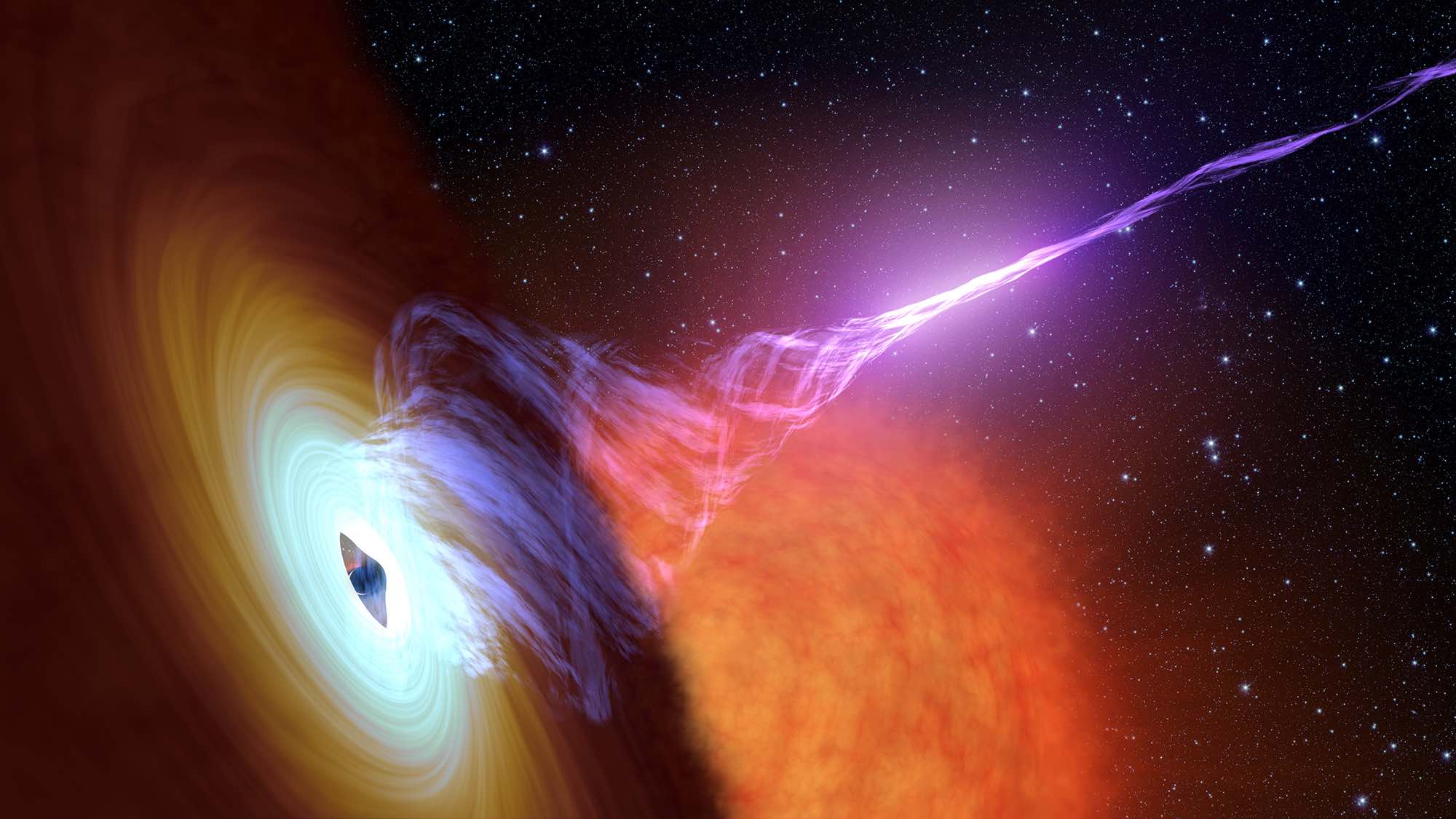
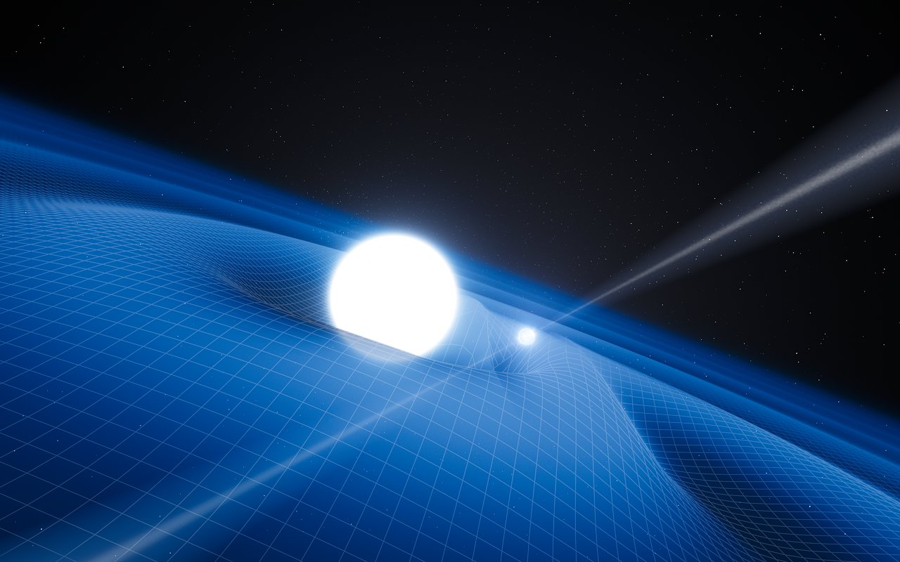
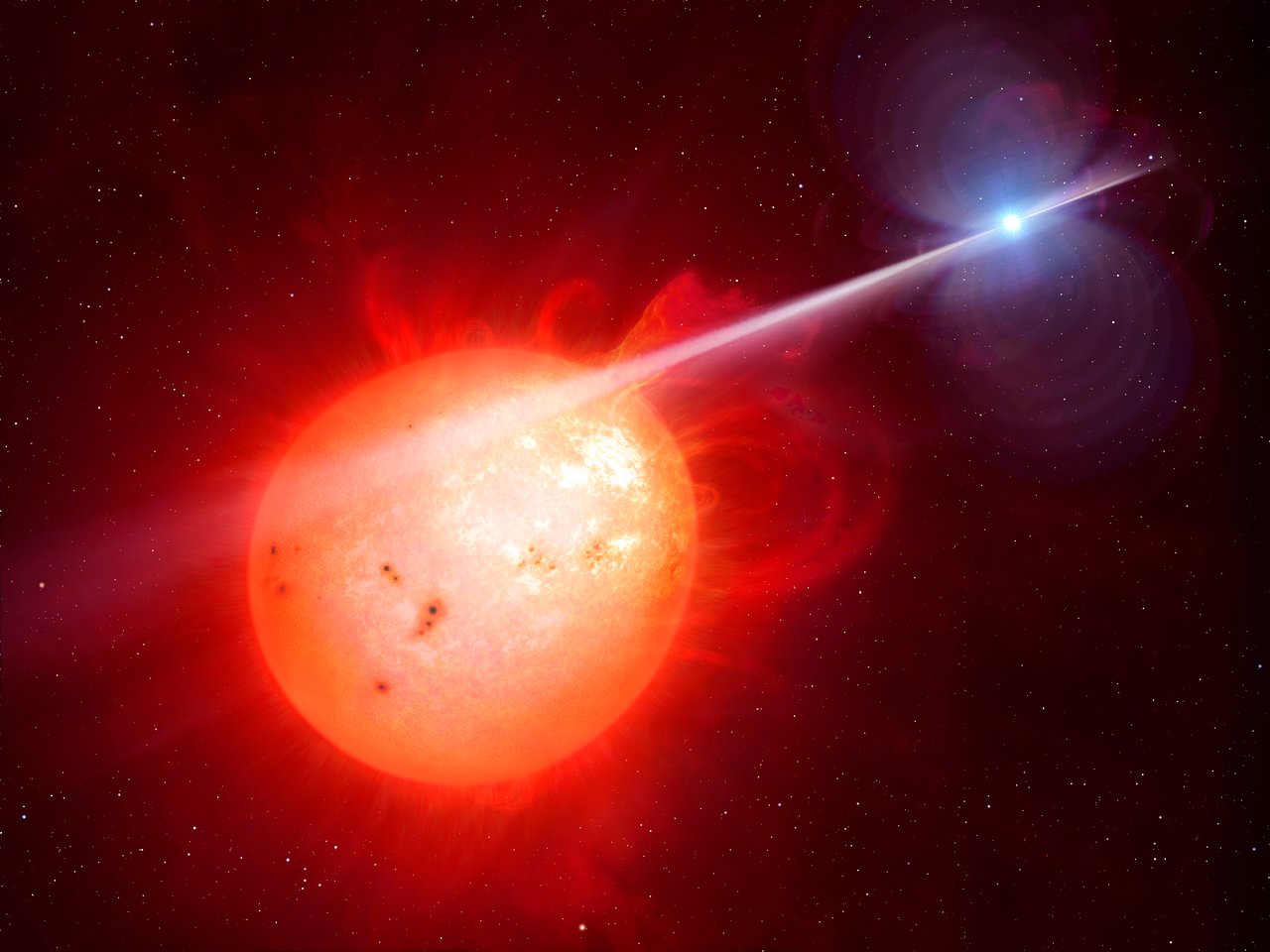

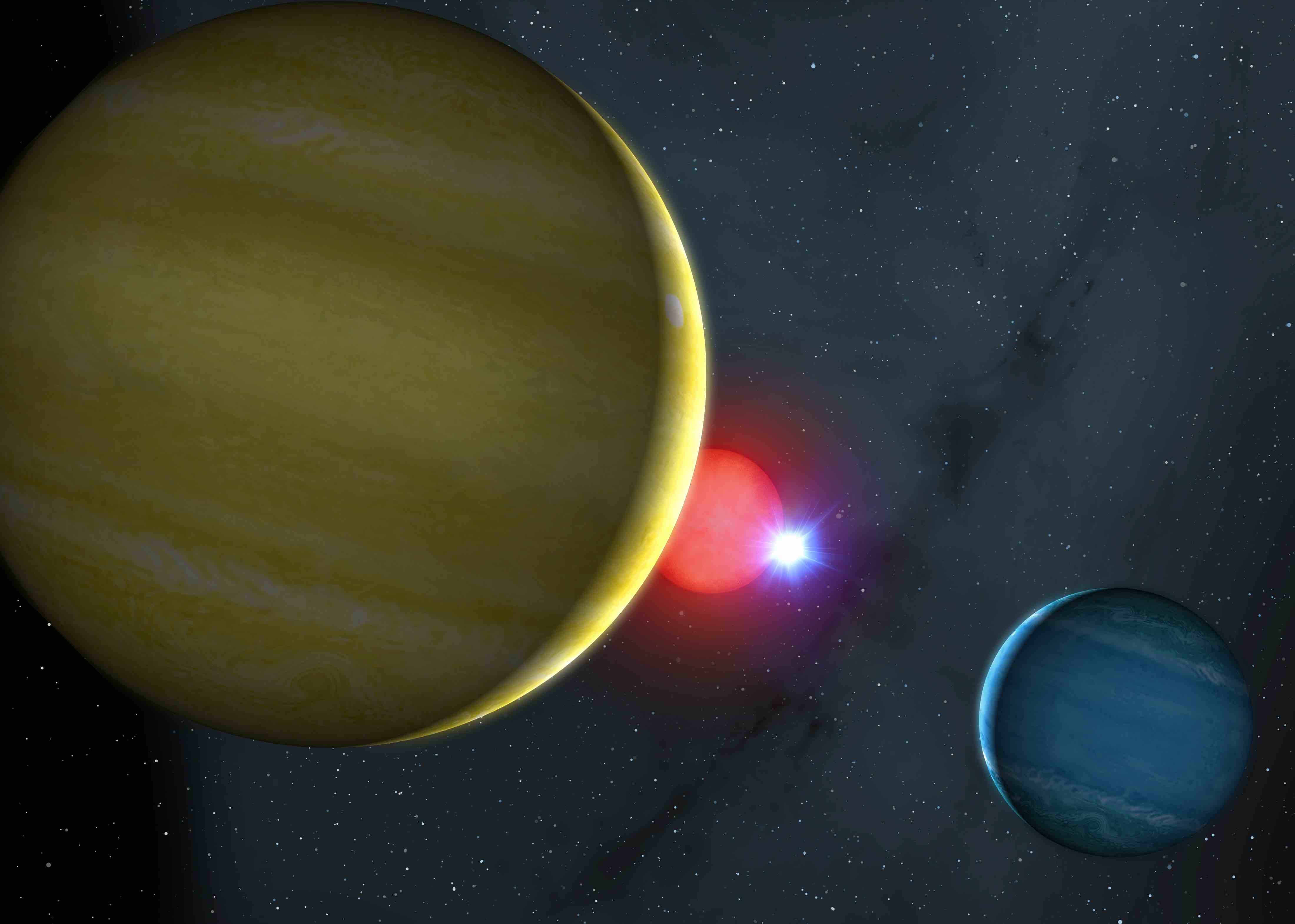

Top-left: Artist's impression showing the jet emanating from the black hole in V404 Cyg. The black hole is surrounded by an accretion disc and orbited by a companion star. Top-middle: Artist’s impression of the pulsar PSR J0348+0432 and its white dwarf companion. The pulsar is a neutron star and is currently the most massive known, with a mass twice that of the Sun. Top-right: Artist’s impression of the exotic binary star system AR Sco, which harbours the first known white-dwarf pulsar. Bottom-left: Artist's impression of the eclipsing cataclysmic variable SDSS 1035+0551, an accreting white-dwarf binary star with the first known brown-dwarf companion. Bottom-middle: Artist's impression of the close white-dwarf/red-dwarf binary star NN Ser - by timing the eclipses of the white dwarf, the existence of two gas-giant planets orbiting the binary was inferred. Bottom-right: Artist's impression of the disintegrating, rocky exoplanet KIC 1255b orbiting its host star. Click on the above images for further information on how high-speed observations helped astronomers to understand these systems.
One of the best ways of studying compact stellar remnants is through their multi-colour photometric variability. The dynamical timescales of black holes, neutron stars and white dwarfs range from milliseconds to seconds. This means that the rotation and pulsation of these objects, and the motion of any material in close proximity to them (e.g. in an accretion disc), tends to occur on such short timescales. Hence, only by observing at high speeds can the variability of compact objects be resolved, thereby revealing a wealth of information, such as their structure, masses, radii and emission mechanisms.
Observing the Universe on timescales of milliseconds to seconds is also of benefit when studying less massive compact objects, such as exoplanets, brown dwarfs and Solar System objects. Despite varying on timescales of minutes rather than seconds, observing the eclipses and transits of exoplanets at high time-resolution improves throughput through the avoidance of detector readout-time, and enables the detection of Earth-mass planets through small variations in transit timing. Simultaneous, multi-band light curves of the transits of exoplanets are sensitive to wavelength-dependent opacity sources in their atmospheres, especially in low-gravity exoplanets, as will be found by the next generation of exoplanet surveys. Within the Solar System, high time-resolution occultation observations enable shape/size measurements and the detection of atmospheres and ring systems, at spatial scales (0.5 milliarcsec) only otherwise achievable from dedicated space missions.
Left: The Galactic black hole binary system V404 Cygni observed in outburst by ULTRACAM during 2015. The video shows a montage of artist's impression with real animated data. Right: A movie showing the eclipse of a white dwarf observed by HiPERCAM on the GTC, sped up 100x. The top-left panel shows the blue image and the bottom-left the red image. (HiPERCAM actually takes images in three additional colours to these, but they are not shown here.) The white dwarf is the star in the middle towards the top of the image. It looks like a single star in the image, but it is actually an unresolved binary star, in which the white dwarf is orbited by a red dwarf in a very tight orbit. The red dwarf eclipses the white dwarf once every 3 hours, resulting in the deep eclipse shown in the right-hand panel. Notice how the white dwarf appears brighter in the blue image than the red image, and shows a much deeper eclipse in the blue than the red. This shows that the white dwarf must be very bright and hot, and the red dwarf very faint and cool. The other two stars in the image are foreground/background stars that are not associated with the binary. By timing how long it takes the light to fade from bright to faint it is possible to work out the size of the white dwarf.
HiPERCAM has been designed to study compact objects of all classes, including black holes, neutron stars, white dwarfs, brown dwarfs, exoplanets and the minor bodies of the Solar System. The resulting data will help us to answer the questions: What are the progenitors of type Ia supernovae, and fast radio bursts? What are the properties of exoplanet atmospheres? What is the equation of state of the degenerate matter found in white dwarfs and neutron stars? What is the nature of the flow of matter close to the event horizon of black holes? What gravitational wave signals are likely to be detected by the next generation of space and ground-based detectors? What are the properties of the dwarf planets in the Kuiper belt?
However, HiPERCAM is much more than just a fast camera. By operating its non-inverted-mode CCDs at -90°C, the dark current is extremely low and uniform, which means that it is also possible to use HiPERCAM to do long-exposure, deep imaging of extremely faint targets. Moreover, the five different wavebands cover the whole of the optical spectrum, ensuring that no optical photons are wasted and enabling the spectral energy distribution of astronomical objects to be determined in a single shot.
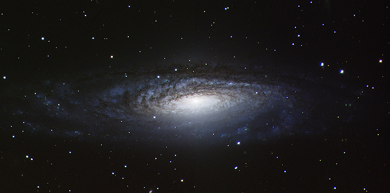
Left: First light with HiPERCAM - the spiral galaxy NGC 7331. This colour image was created by combining the five wavebands recorded simultaneously by HiPERCAM.
A non-technical HiPERCAM infographic by Heloise Stevance can be found here.
Design
The HiPERCAM project began in January 2014, the start date of the €3.5M European Research Council Advanced Grant that funded the instrument. First light took place just under 4 years after this date, on budget and on time. The design of HiPERCAM is based on our successful predecessor instrument, ULTRACAM, but offers a very significant advance in performance, as shown in the following table and described in more detail below.
| ULTRACAM | HiPERCAM | Notes | |
|---|---|---|---|
| Number of simultaneous bands | 3 (ug + r/i/z) | 5 (ugriz) | |
| Readout noise | 3e- at 100kHz | 4.5e- at 263kHz | Dummy output (HiPERCAM) |
| CCD operating temperature | 233K | 183K | |
| Dark current | 360e-/pix/hr | 100e-/pix/hr | |
| Longest exposure time | 30s | 1800s | |
| Highest frame rate | 400Hz | 1050Hz | 24×24 pixel windows, bin 6×6 |
| Field of view on WHT | 5.1' x 5.1' | 10.2'x5.1' | platescale 0.3”/pixel |
| Field of view on GTC | - | 2.8'x1.4' | 0.081”/pixel (HiPERCAM) |
| Probability of r = 10 comparison | 45% | 78% | WHT, galactic latitude = 30° |
| Comparison star pick-off | No | Yes | Under development |
| Dummy CCD outputs | No | Yes | |
| Deep depletion | No | Yes | |
| QE at 700/800/900/1000nm | 83/61/29/5% | 88/78/53/13% | |
| Fringe suppression CCDs | No | Yes | |
| Fringe amplitude in z | >10% | <1% |
Optics
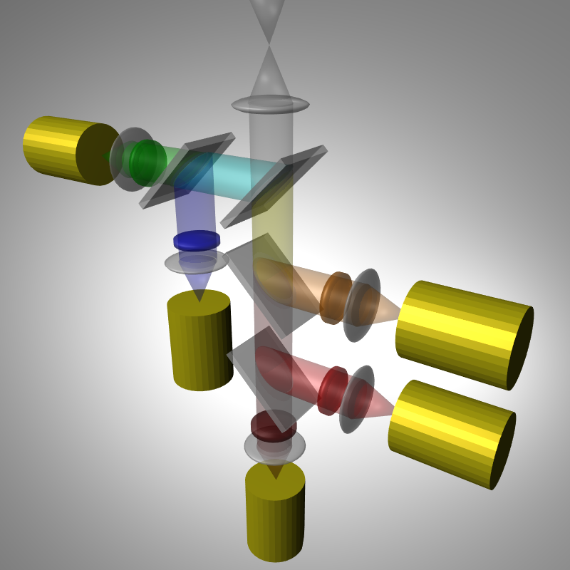
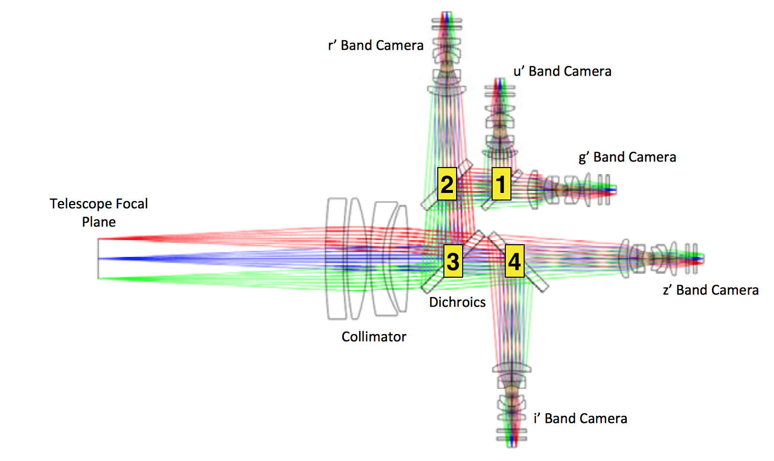
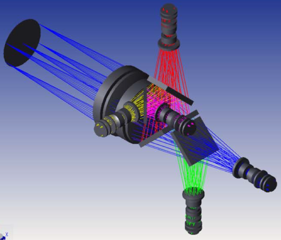
Left: Schematic showing how white light from the telescope is split into 5 colours. Centre: 2D Ray trace through the HiPERCAM optics. The dichroic numbering convention is marked. Right: 3D ray trace showing how the dichroics are rotated to allow more compact packaging of the optics.
Light from the telescope is first collimated and then split into five beams using four dichroic beamsplitters, as shown above. The beam in each arm then passes through a re-imaging camera, which focuses the light through a bandpass filter and detector-head window onto a CCD. The HiPERCAM collimator has been designed for use on both the WHT on La Palma and the 3.5m New Technology Telescope (NTT) on La Silla, giving a platescale of 0.3''/pixel and 0.35''/pixel, and a field of view of 11.4' and 13.4' along the diagonal of the detector, respectively. The same collimator also gives excellent optical performance on the GTC, giving a platescale of 0.081''/pixel and a field of view of 3.1' (diagonal). A new collimator designed specifically for HiPERCAM on the GTC, giving a platescale of 0.113''/pixel and a field of view of 4.3' (diagonal), has been designed but not yet procured.
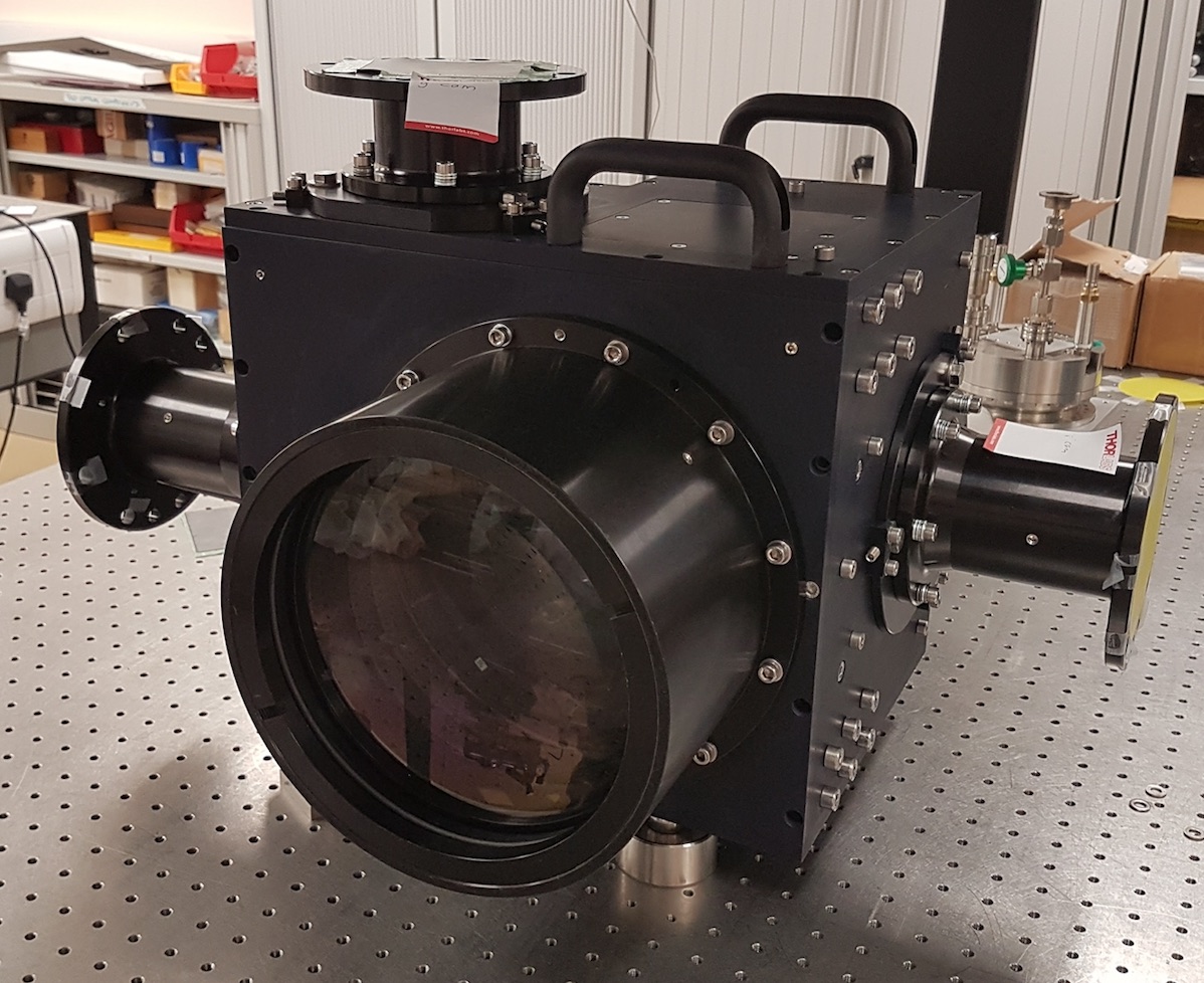
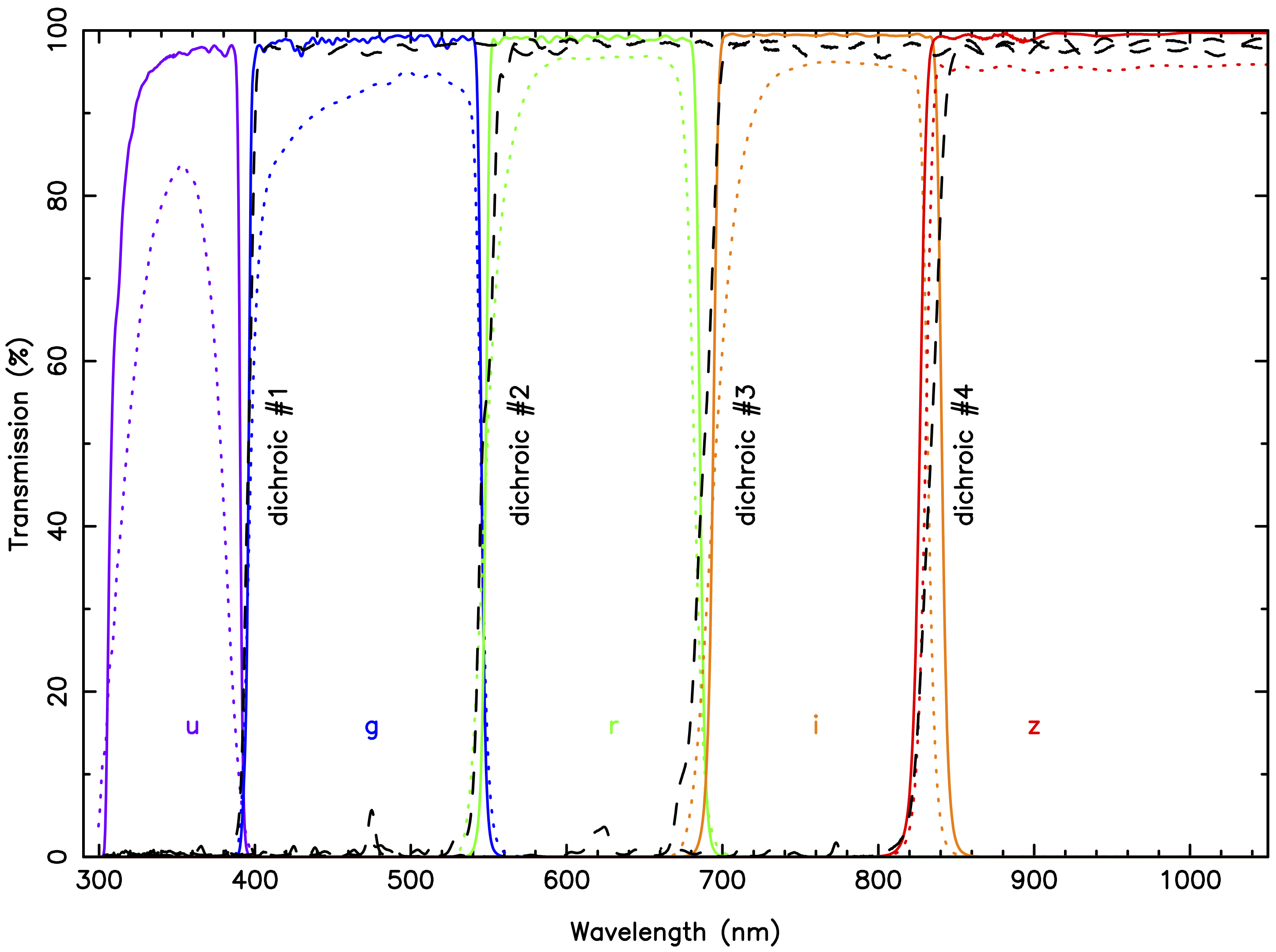
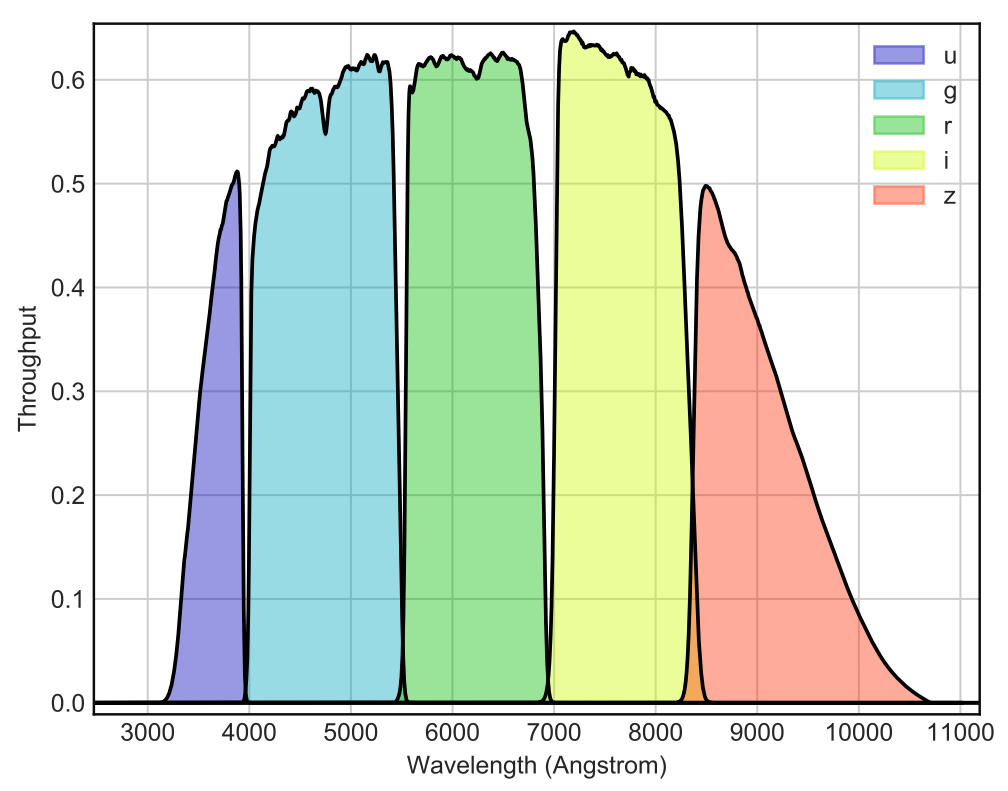
Left: The HiPERCAM hull, housing the four dichroic beamsplitters. The faces of the hull act as mounting points for the collimator and five re-imaging cameras – only three of the camera barrels are visible in this photo. The filter holders and CCD heads are mounted on the ends of the camera barrels. For scale, the large collimator lens visible in the photo has a diameter of 208 mm. Right: As-built transmission profiles of the HiPERCAM “Super” SDSS filters (solid lines), the HiPERCAM “original” SDSS filters (dotted lines), and the four HiPERCAM dichroic beamsplitters (dashed lines).
The dichroics, lens barrels, filters and CCDs are housed in/on an aluminium hull, shown above left, which forms a sealed system to light and dust. The bandpasses of the five arms are defined by a set of so-called "Super" SDSS filters, shown above right, which were designed specifically for HiPERCAM. These filters do not use coloured glasses, but instead rely only on multi-layer coatings to define the filter bandpasses, with the cut-on/off wavelengths designed to match the original SDSS filter set. The percentage improvements in throughput of the HiPERCAM Super SDSS filters, which we call usgsrsiszs, over the original SDSS filters, ugriz, are 41/9/6/9/5%, respectively.
Detectors
The specifications of the five custom-made teledyne-e2v CCDs currently in use in HiPERCAM are detailed below.
| CCD model | Teledyne e2v CCD231-42 |
| Cosmetic grade | 1 |
| Architecture | Split frame transfer, back thinned, 2-phase, NIMO |
| Format | 2048 × 2048 pixels |
| Image area | 2048×1024 pixels |
| Storage area | 2× 2048 × 512 pixels |
| Pixel size | 15μm |
| Outputs | 4 |
| Readout noise | 3.2e- at 200kHz, single-ended |
| Gain | 1.2e-/ADU |
| Dark current | 10e-/pix/hr at 173K |
| Deep depletion Si | is and zs bands |
| AR coatings | Astro Broadband in us, Astro Multi-2 in gsrsiszs |
| Peak QE in usgsrsiszs bands | 76/89/88/88/78% |
| Fringe suppression | is and zs bands |
| Fringe amplitude | ∼0.1% in is and ∼1% in zs band |
| Full well | 120ke- |
| Non linearity | <±0.5% |
| Vertical clocking | 10μs/row |
| Horizontal clocking | 0.1μs/pix, split serial-register |
| Full frame time (bin 1×1) | 3.0s in slow, 1.25s in fast readout mode |
| Full frame time (bin 2×2) | 0.9s in slow, 0.4s in fast readout mode |
| Drift-mode frame time | 0.0009s with 24×24 pixel windows, bin 6×6 |
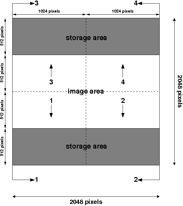
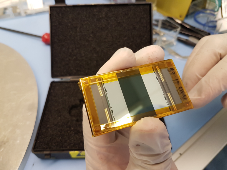
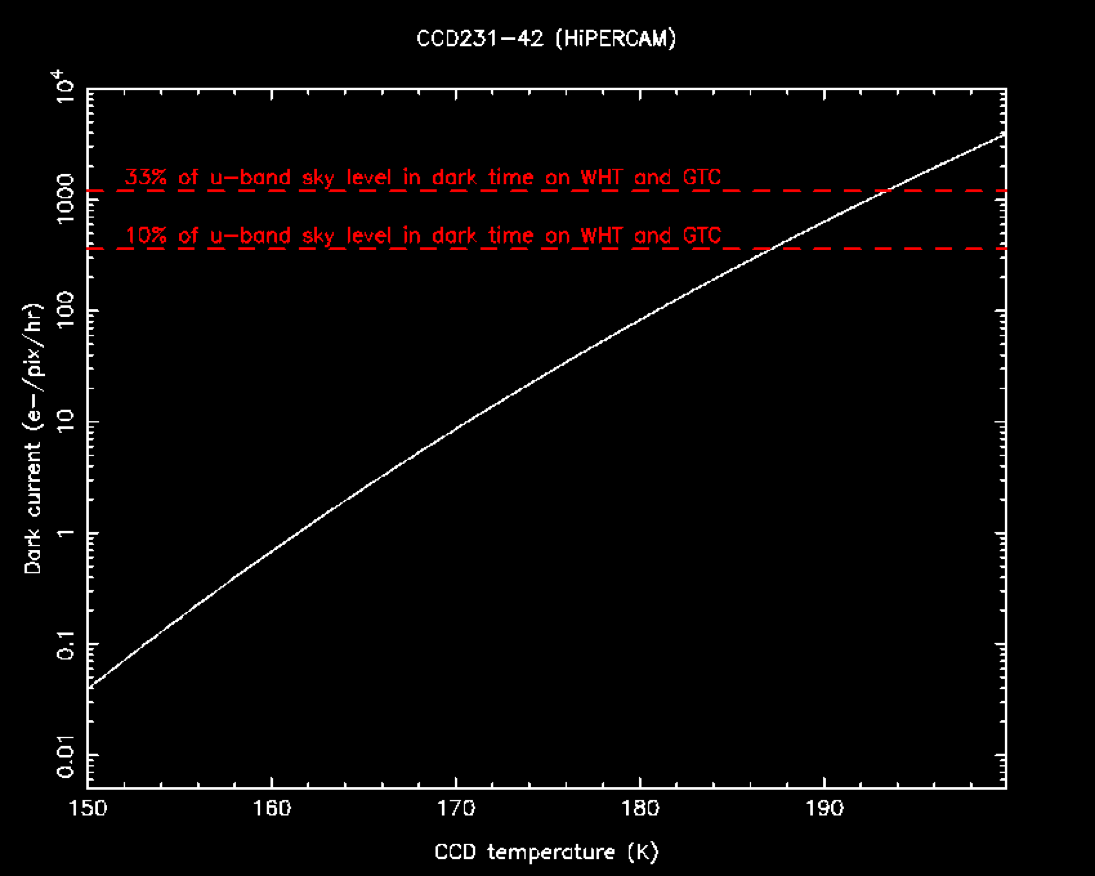
Schematic (top) and photo (middle) of one of the HiPERCAM e2v CCD231-42 detectors. Bottom: Dark current as a function of temperature of one of the HiPERCAM CCDs, showing the target temperature below which dark current is less than the u-band sky level in dark time on the WHT and GTC.
HiPERCAM uses non inverted-mode (NIMO) devices, rather than the inverted-mode (AIMO) devices using in ULTRACAM, for three reasons. First, NIMO devices can be clocked more quickly. Second, although both AIMO and NIMO devices can have similar mean dark current specifications at their optimum operating temperatures, our experience with ULTRASPEC (NIMO) and ULTRACAM (AIMO) is that the dark current in NIMO devices is much more uniformly distributed than in AIMO CCDs; the dark current in the latter is predominantly in the form of numerous hot pixels which do not subtract well using dark frames, making exposures longer than ~30s undesirable. Third, and most importantly, we chose to use NIMO devices in HiPERCAM because we wanted to use deep-depletion silicon in the red CCDs to maximise QE and this in incompatible with inverted-mode operation.
The consequence of selecting NIMO devices for HiPERCAM is that the detectors need to be cooled to below 187K in order to achieve the dark current requirement of <360e-/pixel/hr, which corresponds to 10% of the faintest sky level we can observe with HiPERCAM (set by observations in the u-band in dark time on the GTC). Cooling to below 187K therefore ensures that dark current is always a negligible noise source in HiPERCAM. We looked at a number of cooling options before deciding to use thermo-electric (peltier) coolers (TECs), which are the simplest, cheapest, lightest and most compact of coolers. Our solution uses two Marlow NL5010 five-stage TECs mounted side by side, as shown below. Our detector head design uses all-metal seals rather than o-rings in order to minimize leaks. We went to great lengths to avoid using any materials inside the detector heads that could outgas. So, for example, we mounted the pre-amplifier board outside the head, and used a corrugated indium foil to make good thermal connections between the heatsink, TECs and cold plate. We also reduced outgassing by thoroughly cleaning all components prior to assembly, and then baking the assembled head whilst vacuum pumping. Even with all of these precautions, outgassing limits the vacuum hold time of the HiPERCAM CCD heads to around 1 week, due primarily to the small interior volume of the heads (~0.5 litres) and the lack of a sufficiently cold, large-area interior surface to give effective cryopumping. Fortunately, it only takes a few minutes to pump down the heads whilst on the telescope, thanks to the use of a 5-way vacuum manifold system permanently installed on the instrument.
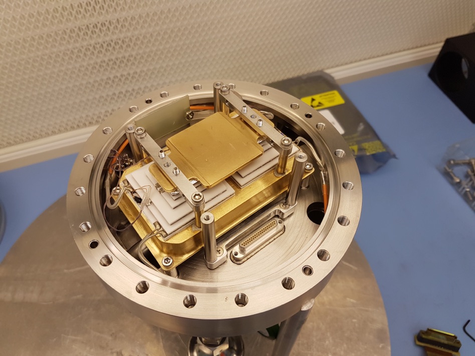
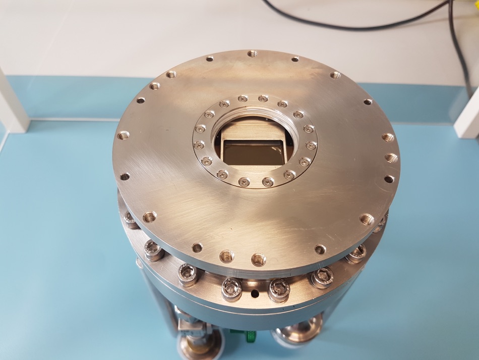
Left: Interior view of one of the HiPERCAM CCD heads, showing the gold-plated cold plate sitting on top of two (white) 5-stage TECs, which themselves are sitting on a gold-plated heatsink through which the cooling liquid runs. Right: Exterior view of one of the HiPERCAM CCD heads. The diameter of the head is 160mm and the weight is approximately 7 kg.
The heat generated by the TECs is extracted using a 278 K water-glycol cooling circuit. To ensure that cooling fluid of the same temperature enters each of the 5 CCD heads, the heads are connected in parallel rather than series, via two 6-way manifolds (the sixth arm is for cooling the NGC controller). Each arm in this parallel circuit is equipped with a flow sensor connected to a Honeywell Minitrend GR Data Recorder mounted in the electronics cabinet. As well as providing a display of the flow rate through each CCD head, the data recorder has relays that can switch off the power to the TEC power supplies if the flow rate in any head drops below a user-defined limit, thereby protecting the CCDs from overheating. As a backup to this system, the TEC power supplies themselves (made by Meerstetter, model LTR-1200) have a high-temperature cut-off facility: if the temperature of the heat-sink in the CCD head rises above a user-defined value, such as would occur if the coolant supply fails, the power to the TEC is automatically shut off. The TEC power supplies are able to maintain the CCD temperatures at their -90°C set points to within 0.01-0.1°C.
In case of high humidity, HiPERCAM has a 5-way manifold that enables clean, dry air from a telescope supply to be blown across each of the CCD windows at approximately 1 litre/min to prevent condensation.
Mechanics
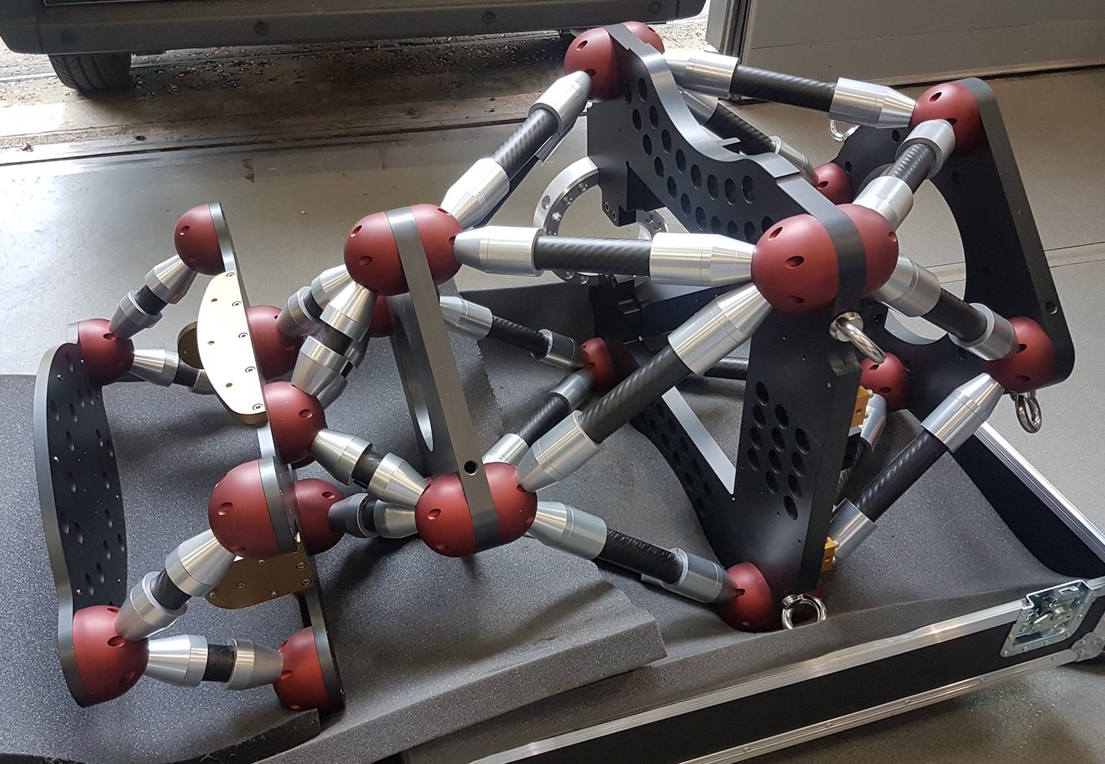
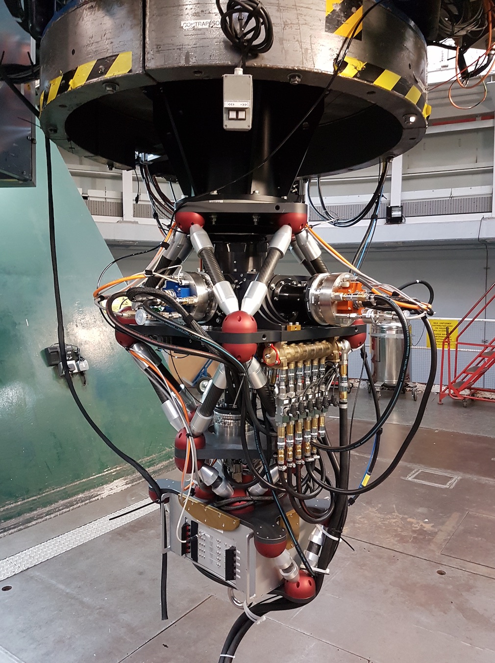
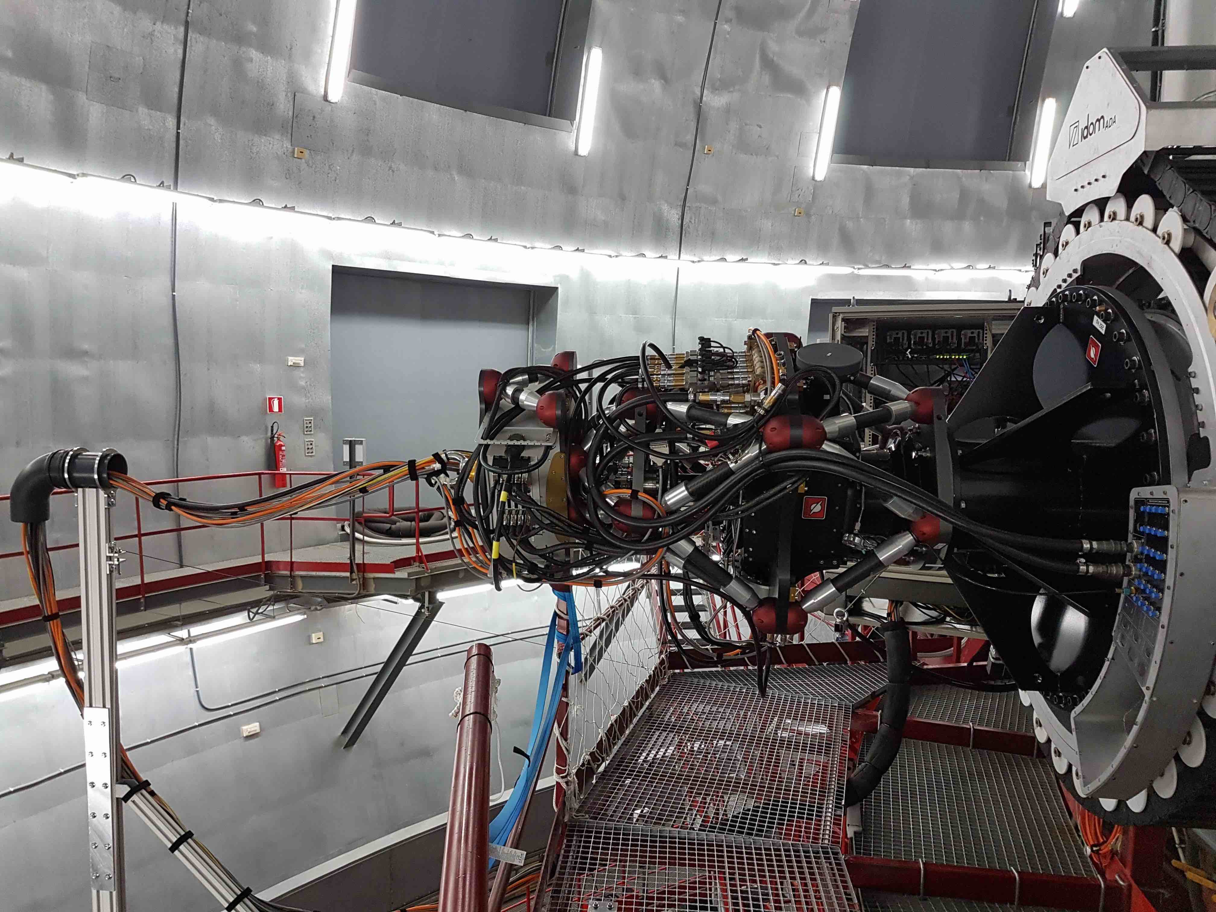
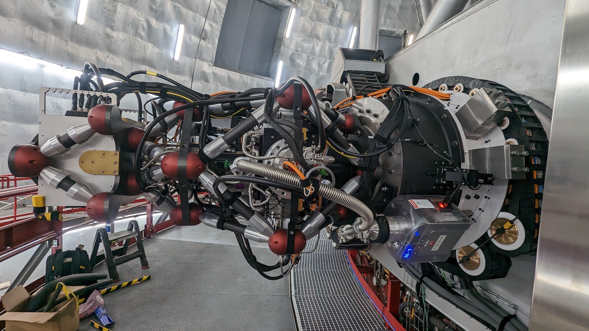
Left: The empty HiPERCAM opto-mechanical chassis sitting in its packing crate. The plate at the right-hand side mounts onto the telescope. The large central plate with a square aperture in it houses the hull. The CCD controller is mounted between the two left-most plates. Centre: HiPERCAM mounted at the Cassegrain focus of the WHT. Right: HiPERCAM mounted on the Folded Cassegrain focus of the GTC.
The HiPERCAM opto-mechanical chassis is a triple octopod composed of 3 large aluminium plates connected by carbon fibre struts, as shown above. This design ensures a stiff, compact (1.25m long), light-weight (280kg) and open structure, which is relatively insensitive to temperature variations. These characteristics make HiPERCAM easy to maintain, transport and mount/dismount at the telescope.
The top plate of the triple octopod is used to mount the instrument onto the telescope, the middle plate is used to mount the hull on and the bottom plate is used to mount the CCD controller onto the instrument. Two different interface collars are used to attach HiPERCAM onto the rotator of the WHT and GTC, and place the instrument at the correct distance from the respective telescope focal planes.
Data acquisition
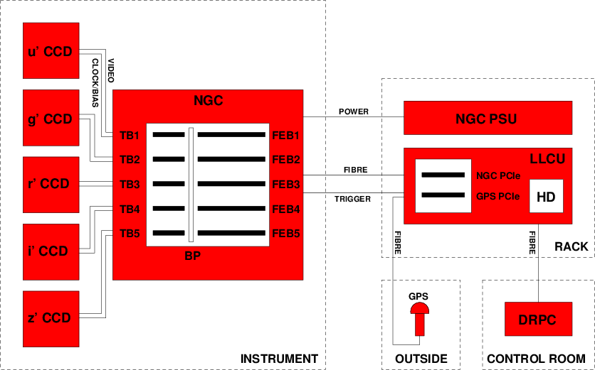
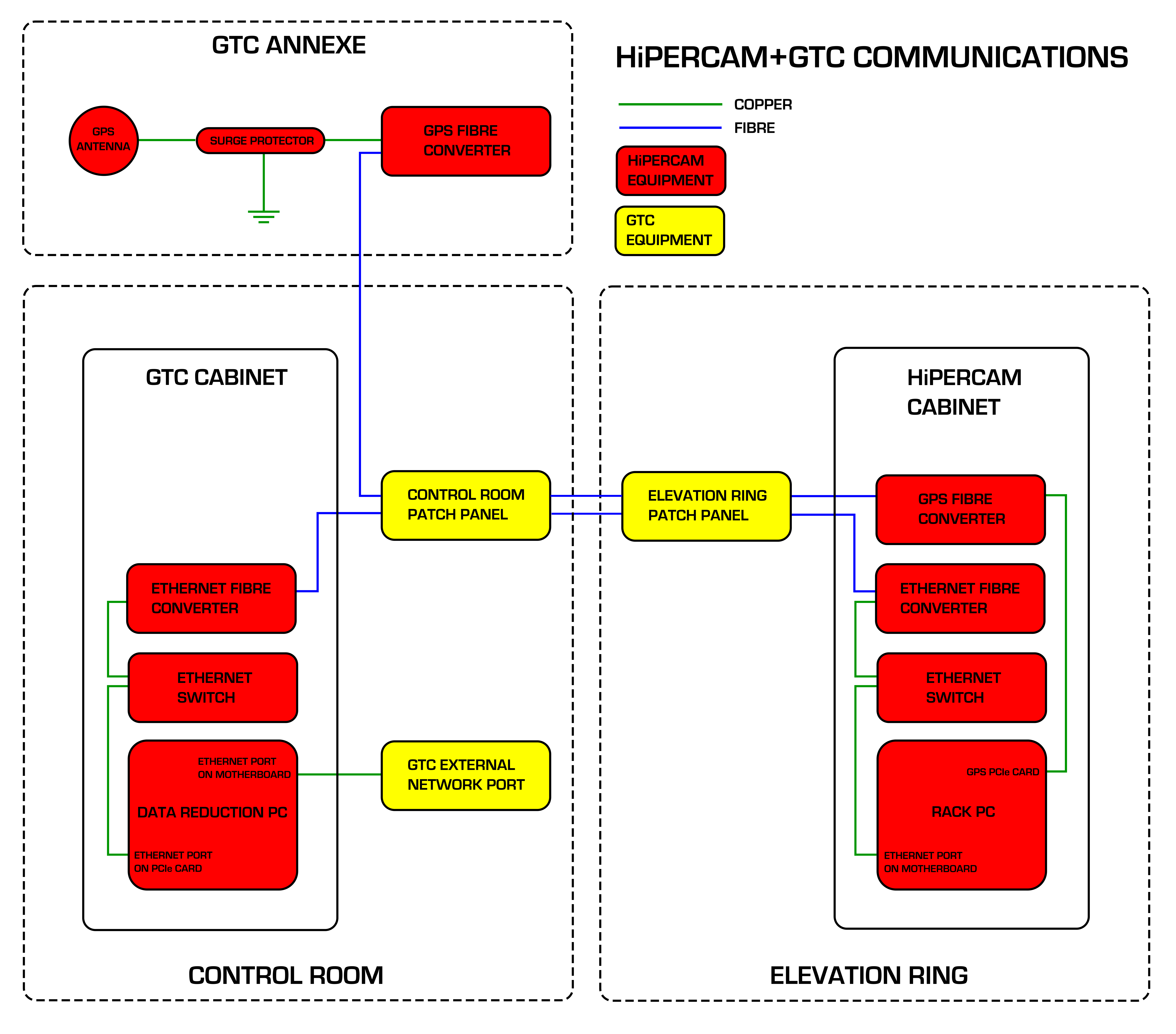
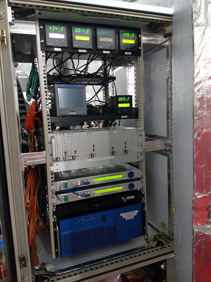
Left: Schematic of the HiPERCAM data acquisition system. Centre: Schematic of the HiPERCAM communication links at the GTC. Right: HiPERCAM electronics cabinet at the GTC. From top to bottom row: pressure displays for CCDs 1-4, flow rate display (left) and pressure display for CCD5 (right), NGC PSU, TEC controller for CCDs 1-3, TEC controller for CCDs 4-5, ESO rack PC.
The HiPERCAM data acquisition system (DAS) is detector limited, i.e. the throughput of data from the output of the CCDs to the hard disk on which it is archived is always greater than the rate at which the data comes off the CCDs. This means that the instrument is capable of running continuously all night at its maximum data rate without ever having to pause for archiving of data.
A schematic of the HiPERCAM data acquisition system is shown above. The heart of the system is a European Southern Observatory (ESO) New General detector Controller (NGC). The HiPERCAM NGC is composed of a six-slot housing containing 5 Front-End Basic (FEB) Boards and 5 Transition Boards (TB). Each FEB is connected to a back plane (BP) and is accompanied by a TB, which handles all external connections to the FEB. Each TB is connected to a CCD head via a single cable, carrying both the clocks/biases from the clock/bias-driver on the associated FEB and the CCD video signal to the four ADC channels on the FEB. The NGC is located on the instrument itself in order to minimise the length of the cables running to each CCD head for noise reduction.
The NGC is powered by a separate Power Supply Unit (PSU), which is located in an electronics rack, approximately 2m away from the instrument. The rack also contains the Linux Local Control Unit (LLCU) for the NGC, which is a linux PC provided by ESO containing the NGC Peripheral Computer Interconnect Express (PCIe) card. The NGC PCIe card is connected to the NGC via fibre, through which it is possible to control the NGC and receive data. In addition to the system disk, the LLCU contains a large-capacity hard disk (HD) on which the raw CCD data are written.
The LLCU also contains a GPS PCIe card, which accepts two inputs. The first input is a trigger that is generated by the NGC whenever an exposure finishes. This trigger will cause the GPS card to write a timestamp to its FIFO (First In, First Out buffer), which is then written to the header of the corresponding CCD frame. The second input is a GPS signal from an external antenna. The external antenna is connected to the GPS card in the LLCU via a fibre-converter that enables a long cable run to outside the dome and isolates the telescope from lightning strikes.
A second linux PC, referred to as the Data Reduction PC (DRPC), is located in the telescope control room. This PC runs, amongst other things, the data reduction pipeline, the instrument-control GUI, the data logger and the target acquisition tool. It is connected to the LLCU via fibre ethernet.
All CCDs are read out simultaneously and have identical exposure start and end times. In order to change the exposure times of the CCDs with respect to each other, it is possible to skip the readout of selected CCDs using the NSKIP parameter. For example, if NSKIP is set to 3,2,1,2,3 for the u,g,r,i,z CCDs, and the exposure time is set to 10s, then the CCD controller will read out only the r-band CCD on the first readout cycle (giving r a 10s exposure), then the g, r and i-band CCDs on the second cycle (giving g and i a 20s exposure), then the u, r and z-band CCDs on the third cycle (giving u and z a 30s exposure), etc.
The HiPERCAM graphical user interface (GUI) is shown below. The top right of the GUI shows three buttons that allows the astronomer to change the readout mode: full frame, windowed or drift mode. Below this are the various CCD readout parameters, giving the astronomer complete control over the detector setup. The number of exposures is usually set to zero in the GUI and the green Start button is then pressed: the data acquisition system will then take data continuously until the red Stop button is pressed. All frames of a HiPERCAM run on a target are written to a single, custom-format FITS file. The HiPERCAM data-reduction pipeline software reads this file and provides a quick-look reduction of the data whilst observing, as shown below. The pipeline is a fully-featured photometry reduction package and so can also be used off-line to produce publication-ready light curves.
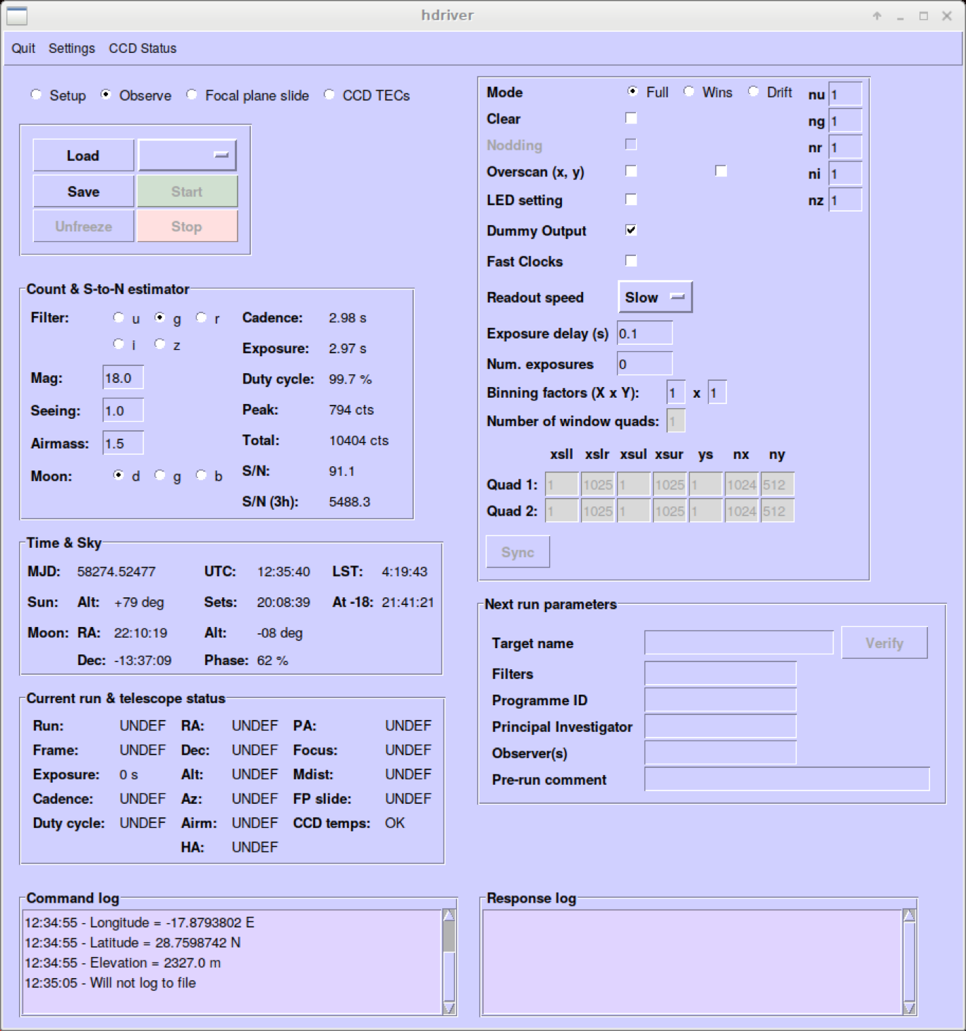
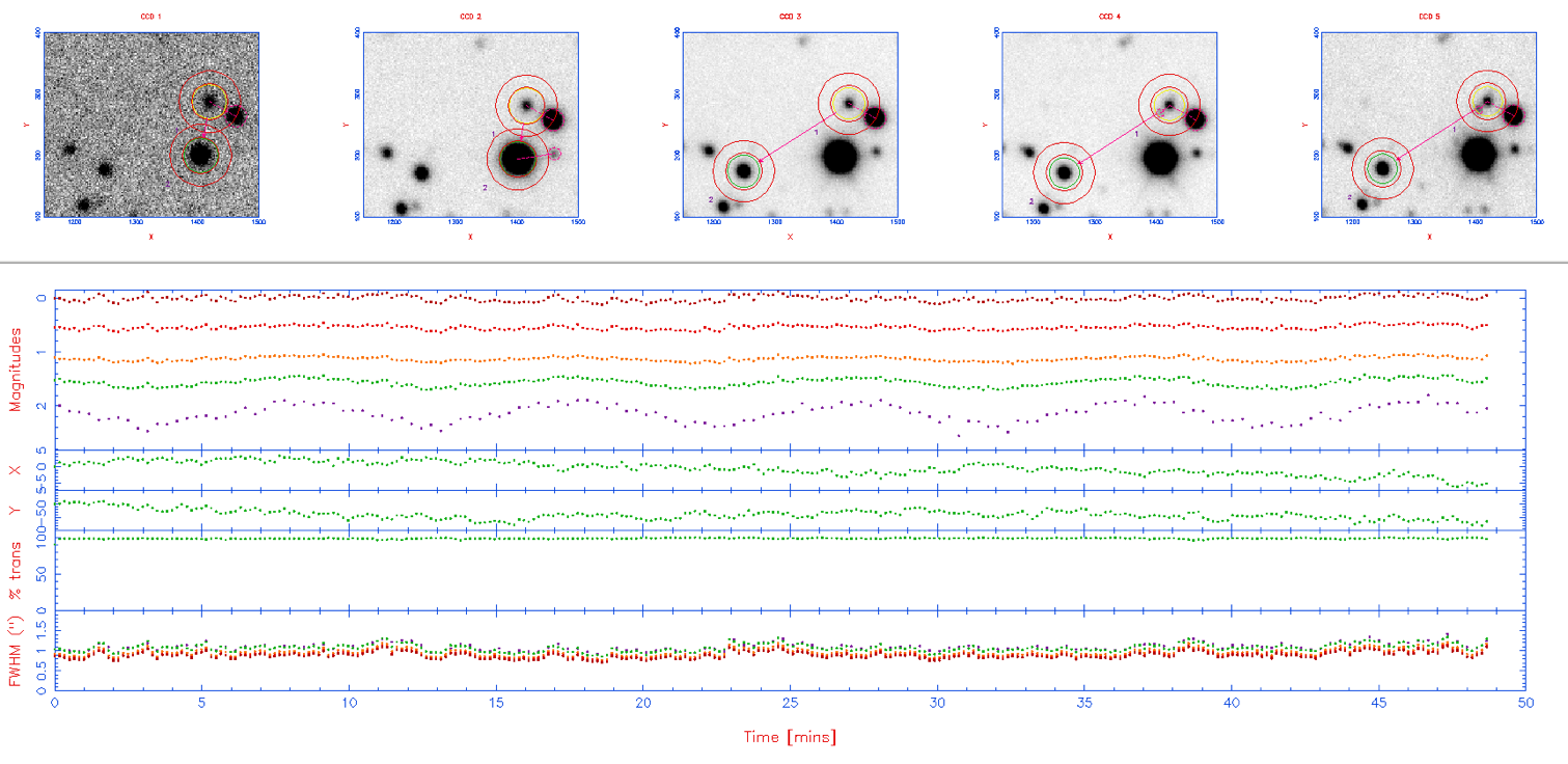
Left: Screenshot of the python-based HiPERCAM GUI, used by astronomers at the telescope to control the instrument. There also exists an engineering GUI for low-level control and telemetry of the CCD controller. Right: Screenshot of the python-based HiPERCAM data reduction pipeline. The top row shows a zoom-in of the usgsrsiszs images of the target and comparison stars, with the apertures defining the object and sky regions superimposed. The bottom panel shows the target minus comparison star magnitudes in usgsrsiszs (top row), the comparison star x,y positions (second and third rows), the sky transparency measured from the comparison star flux (fourth row), and the seeing in usgsrsiszs measured from the comparison-star FWHM (bottom row).
Performance
We commissioned HiPERCAM on the sky for the first time on the WHT during October 2018. This was a short run of only 1 commissioning night and 4 science nights, and was intended primarily to be a shake-down of the instrument prior to commissioning on the GTC. The instrument was then moved to the GTC, where we were allocated 3 commissioning nights and 10 science nights in February 2018. We suffered from terrible weather during this run, and only observed for the last 3 nights, when we completed all of the commissioning. Three more observing runs followed in April, May and June 2018, totalling 16 nights. A wide range of science was performed during this time, including the observation of black holes, white dwarfs, neutron stars, brown dwarfs, extrasolar planets/asteroids, AGN, FRBs, GRBs, SNe and ultra-diffuse galaxies. The performance of HiPERCAM on the GTC is reported below.
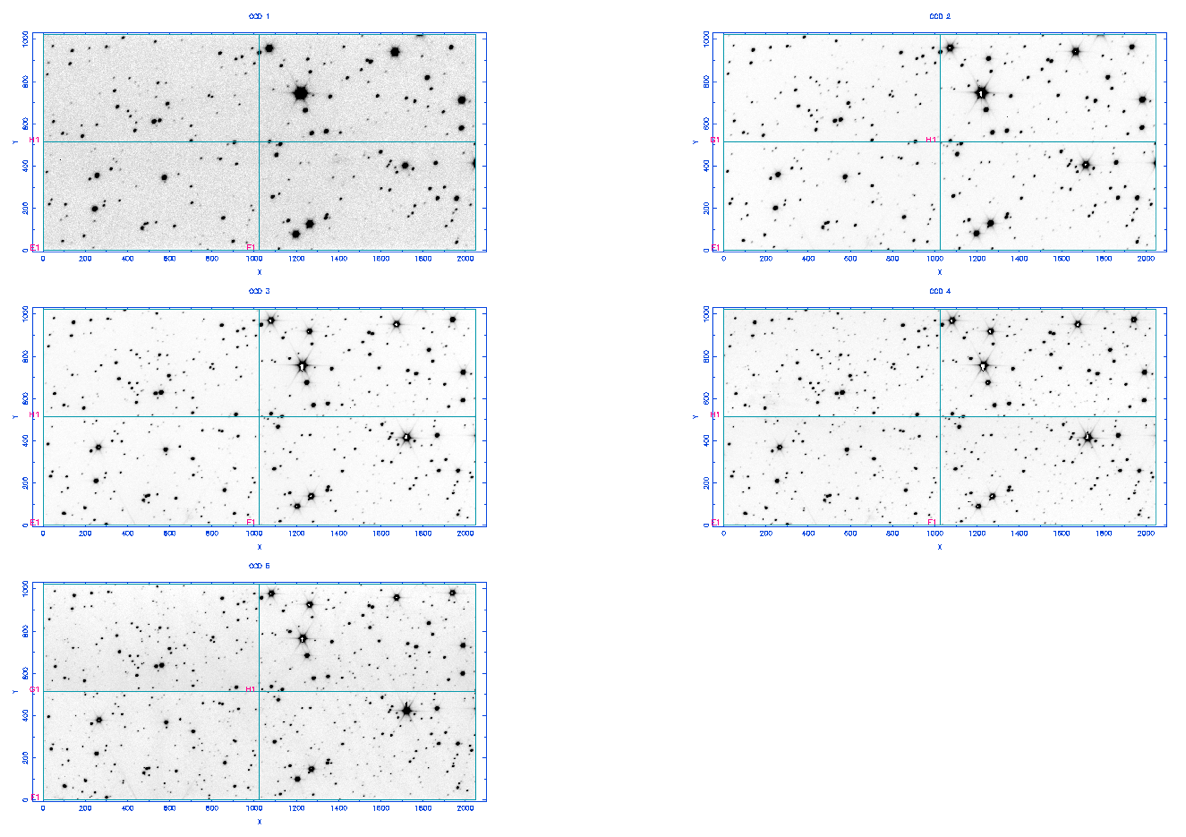
Images of a star field obtained with HiPERCAM on the GTC in us and gs (top row), rs and is (middle row), and zs (bottom row).
An example star field observed with HiPERCAM on the GTC is shown above. The FWHM of the stars in these images are us = 0.56'', gs = 0.44'', rs = 0.41'', is = 0.37'', us = 0.36'', with no discernible variation with field angle. This indicates that HiPERCAM on the GTC can provide seeing-limited images across the whole field of view in even the very best seeing conditions on La Palma. Since the dichroics operate in a collimated beam and have anti-reflection coatings on their rear surfaces, we do not expect to see any ghosting in our images, and this is indeed the case: a careful inspection of the brightest stars in the above images reveals no discernible ghosting. The pixel positions of the stars at the corners of the field of view are the same on all 5 CCDs, to within approximately 5 pixels (75μm), indicating that there is no discernible variation of platescale with wavelength and that the CCD heads are well aligned with respect to each other. Twilight-sky flat fields show no discernible vignetting in the corners of the field of view.
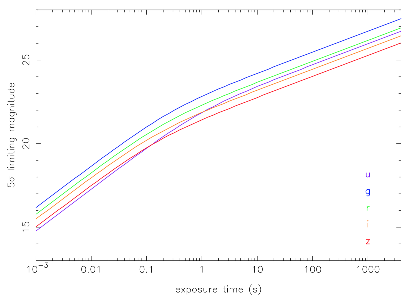
Limiting magnitudes (5σ) of HiPERCAM on the GTC as a function of exposure time. The purple, blue, green, orange and red curves show the results for the usgsrsiszs filters, respectively. The calculations assume dark moon, observing at the zenith and seeing of 0.8”.
The measured photometric zero points of HiPERCAM on the GTC, defined here as the magnitude of a star that would give 1 electron per second above the atmosphere, are: us = 28.17 (25.76), gs = 29.25 (28.71), rs = 28.76 (29.05), is = 28.43 (28.60), zs = 27.95 (28.04). The numbers in brackets show the corresponding values for OSIRIS, the common-user, single-channel optical imager at the GTC. These two sets of zero points were measured within a few days of each other during May 2018, using observations of SDSS standard stars. It can be seen that unless one needs the full 7.8' field of view of OSIRIS, or just one of the redder bands, it is much more efficient to use HiPERCAM for standard imaging at the GTC, and one would also gain from the huge reduction in dead time between exposures (0.01s with HiPERCAM, 21s with OSIRIS).
The 5σ limiting magnitudes of HiPERCAM on the GTC are shown above as a function of exposure time, calculated using the zero points listed in the previous paragraph. It can be seen that it is possible to achieve a limiting magnitude of g ~ 16 in a single 0.001s exposure, g ~ 23 in 1s, and g ~ 27 in 1800s.
Throughput curves for HiPERCAM in usgsrsiszs. These curves do not include the atmosphere or telescope.
The throughput curves of HiPERCAM, which include all optics and CCDs but not the atmosphere and telescope, are shown above. The throughput peaks at over 60% in gsrsis and 50% in uszs. This high throughput has been achieved by using high-performance multi-layer coatings on the lenses, dichroics, filters and windows, as well as CCDs optimised for operation in each band.
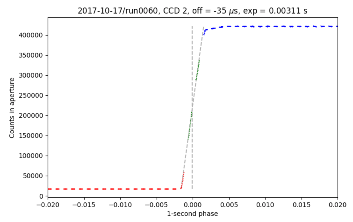
Phase-folded light curve of an LED attached to the PPS output of the HiPERCAM GPS system.
We measured the accuracy of the GPS absolute timestamping of each CCD frame in HiPERCAM by observing an LED connected to the pulse-per-second (PPS) output of our GPS system. An example observation is shown above, where we plot the light curve of the LED phase-folded on its 1s period. The shape of the light curve is a convolution of two top-hat functions, one for the LED pulse and the other for the exposure time duration (in this example, 0.003s). Hence the folded light curve exhibits a ramp, the centre of which should correspond to the start of the GPS second. The figure above shows that this is indeed the case: the offset between the start of the GPS second and centre of the ramp is only 35μs and is set by the measurement accuracy of our experiment. Hence we can say that the absolute timestamping of each CCD frame in HiPERCAM is accurate to better than tens of microseconds.
Future enhancements
THESE HAVE NOW ALL BEEN IMPLEMENTED - SEE NEWS
HiPERCAM was removed from the GTC rotator in June 2018 so that an autoguider could be installed. The instrument was remounted on the telescope in September 2018, where it will remain in use for science until January 2019. In 2019, HiPERCAM will share the Folded Cassegrain focus of the GTC with CanariCam. The situation from 2020 onwards is less clear at the moment, due to the arrival of MIRADAS at the GTC.
We are planning on making four enhancements to HiPERCAM during the coming year or two. The first is to modify the CCD preamp boards so that it is possible to switch the bandwidth from the current value of 1.06MHz to approximately half and/or quarter this value. In this way, we hope to reduce the readout noise from its current value of ~4e- to ~3e- in slow readout mode (263kHz).
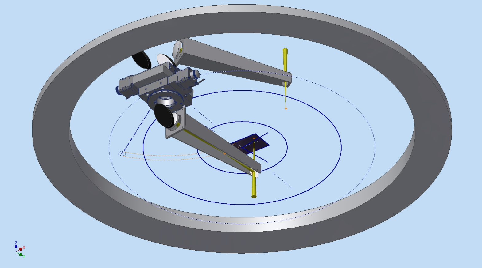
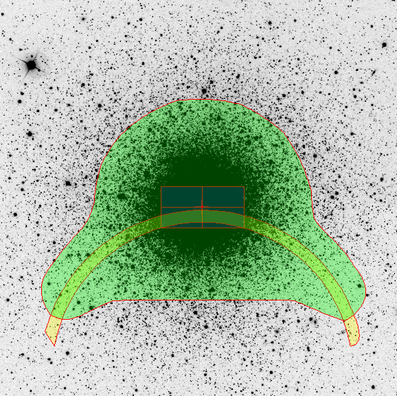
Left: CAD image of COMPO. The upper arm collects light from a star falling outside the HiPERCAM field of view (solid blue rectangle at centre) but inside the 10’ diameter view of view at the Folded Cassegrain focus of the GTC (outer blue circle). The lower arm redirects this light to one of the corners of the HiPERCAM field of view, via a set of relay optics. Right: An example finding chart showing the HiPERCAM field of view (red rectangle at centre) and the entire GTC field of view (green "upside-down Mickey Mouse" shape). The yellow arc shows the area of sky available to COMPO at a given telescope rotator angle. The whole pattern depicted in this image rotates around the red dot at the centre as the telescope rotator is moved.
The second enhancement is to implement a COMParison star Pick-Off system (COMPO), as shown above. Light from a bright comparison star that falls outside the 3.1' diagonal field of view of HiPERCAM, but within the 10' diameter field of view of the Folded Cassegrain focus of the GTC, is collected by a pick-off arm. The light is then redirected to a second arm, via a set of relay optics, which injects the starlight onto one of the corners of the HiPERCAM CCDs. In this way it is possible to use much brighter comparison stars than would usually be available for differential photometry. This will be of particular importance when observing bright targets, like exoplanet host stars, for which nearby comparison stars of comparable or greater brightness are rare. More quantitatively, without COMPO, there is a 90% probability of finding a comparison star of magnitude r = 14 in the field of view, whereas with COMPO one will be able to find comparison stars of magnitude r = 12 with the same probability. COMPO will also be of great benefit to most us-band observations, as many of the targets observed by HiPERCAM tend to be blue (e.g. white dwarfs) and hence bright in the us-band, whereas most comparison stars tend to be red and hence faint in the us-band.
The third enhancement is to procure a diffuser and place it in front of the collimator. This will provide stable PSFs covering a large number of pixels in order to reduce the systematic photometric errors induced by seeing and pixel sensitivity variations. In November 2019, we successfully tested a prototype diffuser with HiPERCAM on the GTC, as shown in the photographs below.
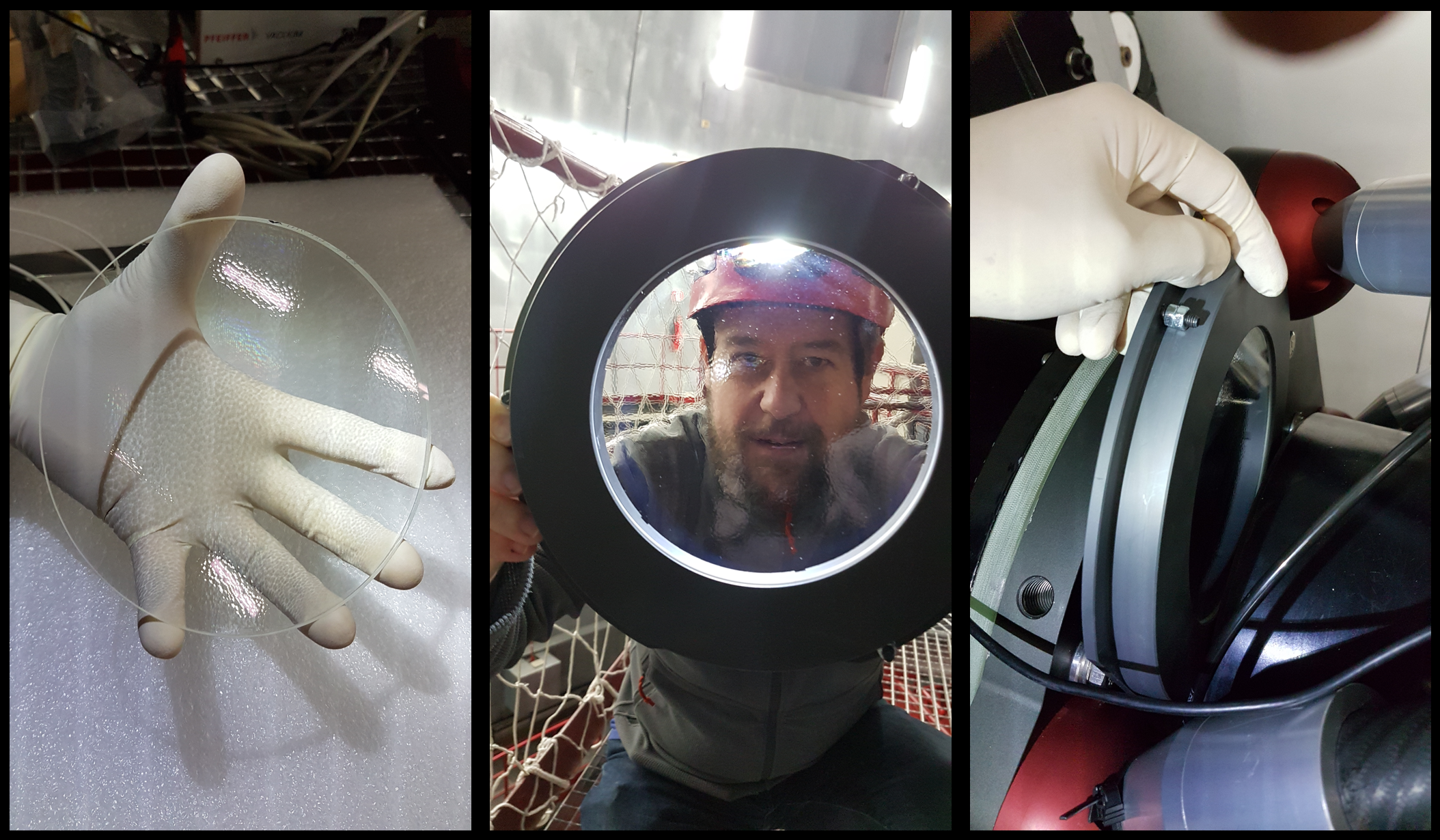
From left to right: The prototype diffuser, the diffuser mounted in its cartridge, and the cartridge being installed into its holder in front of the collimator.
The fourth enhancement is to design and procure a new rotator at the unused Folded Cassegrain focii of the GTC adjacent to MEGARA, shown below, thereby giving HiPERCAM a permanent home at the GTC. A straight copy of the existing GTC rotator design will not work due to space limitations, as also shown below. Funding has just been secured to bring this project to the Preliminary Design Review stage, which is expected to be held in mid-2019.
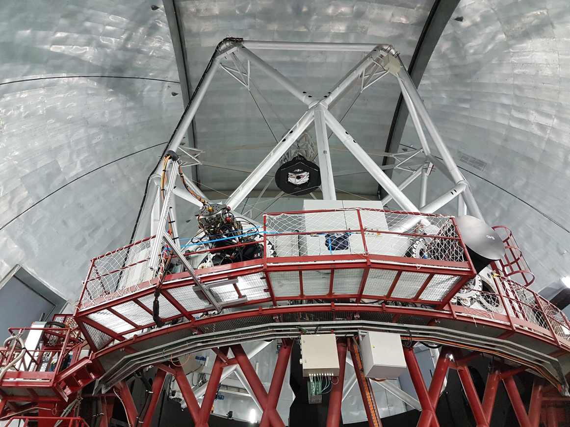
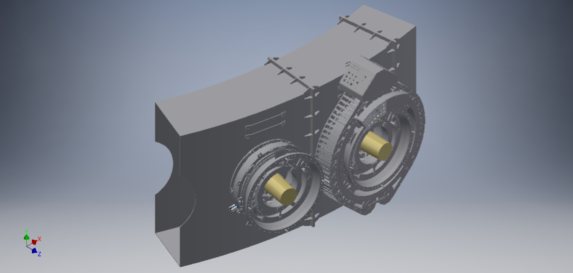
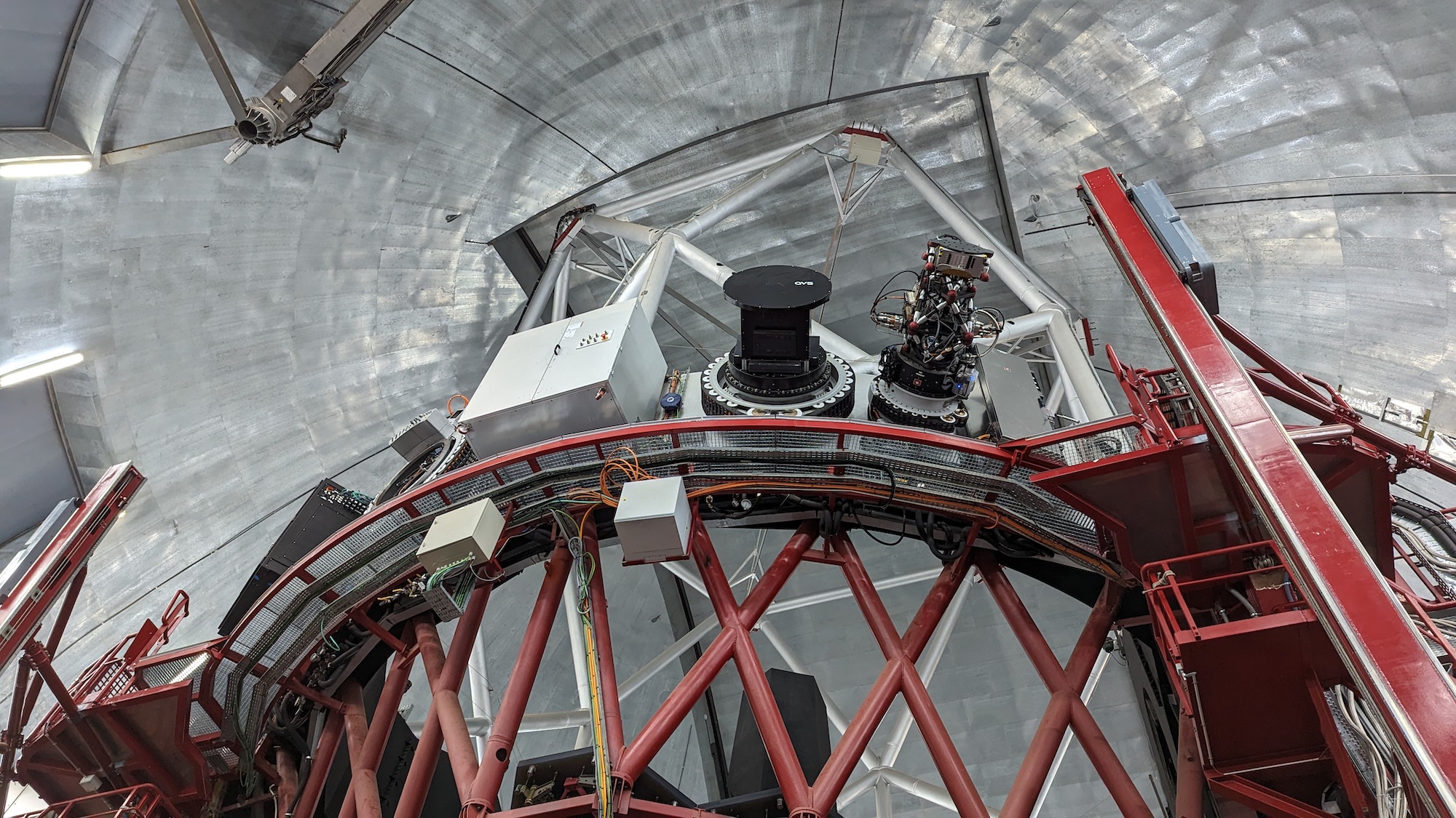
Left: The elevation platform of the GTC, showing the 4 Folded Cassegrain focii, with HiPERCAM on one of the left-hand ports. The black cylinder on one of the right-hand ports houses MEGARA, and the proposed new focus for HiPERCAM is just to the right of this. Right: CAD image showing two of the adjacent Folded Cassegrain focus. The right-hand port is equipped with the existing GTC rotator design, whilst the left-hand port has an identical copy of this, but without the cable wrap mechanism. It can be seen that the two rotators touch each other, and hence a smaller, custom rotator will have to be designed and built for HiPERCAM.
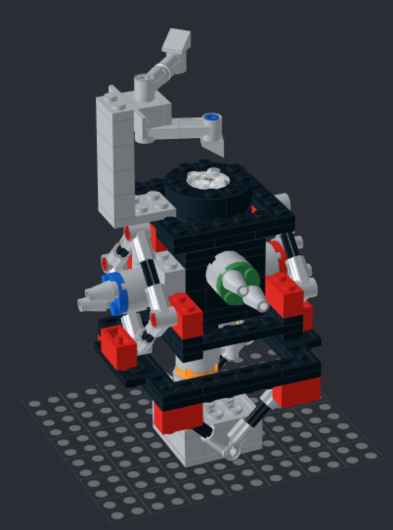
Most importantly, we now have a Lego model of HiPERCAM, courtesy of Martin Black at UKATC. You can view and modify the model using Studio 2.0. If you want to build your own HiPERCAM, upload the model to bricklink, where you will be able to buy the bricks.