| charge coupling |
|
The unique feature of a CCD, which gives it its name, is the way in which the photo-electrons are extracted from the storage site, a process known as charge coupling.
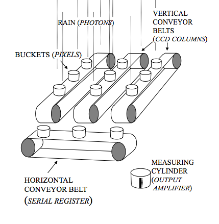
Once the CCD has been exposed to light for the required amount of time, each pixel will contain a charge packet of size proportional to the number of incident photons. To measure this charge, it is necessary to move these charge packets, one by one, off the chip. The easiest way of visualizing this process is by thinking of taking a CCD image as analogous to measuring the rain falling on a field, as shown in figure 106. The first step is to distribute a large number of buckets in a rectangular pattern of rows and columns over the field - these are the pixels. After it has stopped raining, you can measure the amount of water collected in each bucket, i.e. the amount of charge in each pixel, by shifting the entire array of buckets, one row at a time, on parallel conveyor belts towards a perpendicular conveyor belt at one end of the field. When a single row has been transferred onto the conveyor belt at the end of the field, the row is shifted, one bucket at a time, towards a measuring point at the end of this conveyor belt, where the amount of water in each bucket is recorded. Once the whole row has been measured, the next row is shifted onto the conveyor belt at the end of the field, and the process is repeated until every bucket in the field has been measured. By plotting the amount of rain in each bucket as a two-dimensional grey-scale image, where white represents a full bucket and black an empty one, it is possible to visualise the pattern of rainfall over the field. Replacing the rain in this analogy by photons, this is how an image of the sky can be recorded.
| figure 106: |
schematic (left) and
animation (right; reload page to restart) showing the analogy between
constructing an astronomical image with a CCD and measuring the rainfall
over a field - see text for details.
|
So how are the conveyor belts implemented electronically? We saw in figure 104 that the pixels in most CCDs are defined by three electrodes. This so-called three-phase structure can be exploited to move charge. The voltage in an electrode adjacent to the electrode holding the charge packet is raised to the same level. This allows the charge to flow, like water, and be shared between the two electrodes. Decreasing the voltage of the original electrode then completes the transfer, pushing all of the charge across to the adjacent electrode, which is held at the higher voltage level. Since there are three electrodes in each pixel, three of the above transfers are required to move the charge packet by one pixel. The process of raising and lowering the voltages to move charge is known as clocking, and is illustrated in figure 107. The clock pulses can be described by a timing waveform, also shown in figure 107, and are straightforward to implement electronically.
| figure 107: |
schematic
(left) and animation (right) showing how charge is clocked
from one pixel to the next by modulating the voltage on adjacent electrodes.
|
The process of transferring charge from one electrode to the next
is not perfect. The charge transfer efficiency, CTE, is defined by
the equation:
CTE = 1 - [(N0 - Nt) / N0],
where N0 is the number of charges under an
electrode and Nt is the number transferred to the
next electrode. It is essential to have extremely high values of CTE
in an astronomical CCD. For example, if there are 1000 e-
under an electrode and the CTE is 99%, then after 100 transfers only
1000 x (0.99)100 = 366 e- = 36.6% of the
original charge will have been transferred! The net effect is to trail
the image of a CCD in the direction of the charge transfer. In
practice, CCDs with CTEs greater than 99.999% are required, as
demonstrated in the example
problems.
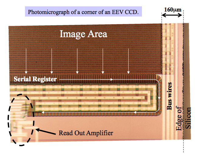
Figure 108 shows the structure of a typical CCD. The electrodes in the main image area of the CCD, known as the parallel register, are arranged so that they move the charge vertically downwards (a process known as vertical clocking). At the bottom of the parallel register is a single row, the serial register, in which the electrodes are arranged perpendicularly to those in the parallel register, so that they move the charge horizontally (a process known as horizontal clocking). At the end of the serial register is an output amplifier.
| figure 108: |
Left: the structure of a CCD, indicating the parallel register, serial
register and output amplifier. Right: photomicrograph of the corner of a CCD, with arrows showing the
direction in which the charge is shifted. In this particular CCD, the serial
register is bent double to move the output amplifier away from the edge of the chip, which is useful if the CCD is to be butted against another in a mosaic.
|

A
complete clocking sequence, known as a read out, therefore
consists of the following steps: