| reflectors |
|
A spherical concave mirror can be used to collect the light from an astronomical object and image it, as shown in figure 11. Since mirrors use reflection rather than refraction to form an image, they are inherently free of the most destructive aberration of all - chromatic aberration. Mirrors are also simpler than lenses in that they have only one optical surface. The optical properties of the substrate are unimportant: mirrors are usually made of a rigid, hard (i.e. polishable) material with a low thermal expansion coefficient (such as the glass Pyrex or the glass-ceramic Zerodur), and coated with a thin layer of aluminium, silver or gold to give high reflectivity. A telescope which uses a mirror to collect and focus light is known as a reflector.
spherical aberration
Unfortunately, mirrors are not aberration free. The top panel of figure 11 shows that the rays from the edge of a spherical mirror come to a focus nearer the mirror than do rays from the centre of the mirror, causing a point source to be imaged as a blurred disc. This defect is known as spherical aberration.
| figure 11: |
The top panel is a schematic showing how a spherical concave mirror can
collect light and bring it to a focus. The resulting image suffers from
spherical aberration, but this can be removed using a parabolic mirror,
as shown in the bottom panel.
|
The effects of spherical aberration in mirrors can be reduced by positioning the focal plane coincident with the circle of least confusion, as shown in figure 11, but this still leaves an unsatisfactory blurring of the image. However, the Scottish astronomer James Gregory realised in 1663 that spherical aberration can be eliminated if the curve of the surface of a mirror is a parabola. This is also shown in figure 11, where all rays parallel to the axis of a parabolic mirror are reflected to meet at the focus of the parabola.
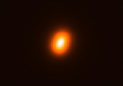
Creating mirrors with parabolic surfaces is not straightforward, as special grinding and polishing techniques are required in order to create the deeper central depression of a parabola compared to a spherical surface. A famous example of spherical aberration is given by the Hubble Space Telescope (HST), which suffered from spherical aberration due to a mistake during the manufacture of its (hyperbolic) 2.4m mirror, as shown in figure 12. Corrective optics were later installed by astronauts on a space shuttle servicing mission and the telescope is now functioning perfectly.
| figure 12: |
Left: Image
of a star taken with the HST, showing the blurred,
circularly-symmetric image characteristic of spherical aberration.
Right: Image of a star taken with the corrected HST, showing just the
Airy disc and
diffraction rings, indicating that the spherical aberration has been
successfully removed: the image of the star on the left covers approximately
2 arcseconds, whereas that on the right covers only 0.05 arcseconds.
|
It should be noted that lenses, and hence refractors, suffer from spherical aberration in exactly the same way as mirrors, but it is a much smaller effect than chromatic aberration. Spherical aberration can be eliminated from refractors using aspheric lenses, in which the curvature of the surfaces is not constant, but these are difficult and expensive to produce. It is more common to remove spherical aberration from refractors by designing achromats in such a way that the negative lens cancels out the spherical aberration introduced by the positive lens, whilst still correcting for chromatic aberration. [It is even possible to design achromats which also correct for coma (see below) - so called aplanatic lenses].
coma, astigmatism, curvature of field and distortion of field
Until now, we have been considering only on-axis aberrations, such as chromatic and spherical aberration. These are the aberrations suffered when imaging a point source in the centre of the field of view. There also exist off-axis aberrations, such as coma, astigmatism, curvature of field and distortion of field. These are caused when the light rays are not parallel to the optical axis, i.e. when imaging objects towards the edge of the field of view. We shall look at each of these aberrations in turn, before going on to describe the various different types of reflecting telescopes that have been designed to combat them.
It is important to note that all four of these off-axis aberrations affect both mirrors and lenses, and hence both refracting and reflecting telescopes. It should also be noted that all the aberrations we look at in this course are inherent to the lens or mirror; there exists another whole class of aberrations which result due to poorly manufactured, badly mounted and mis-aligned optics which we shall not consider here.
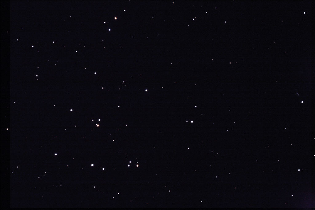
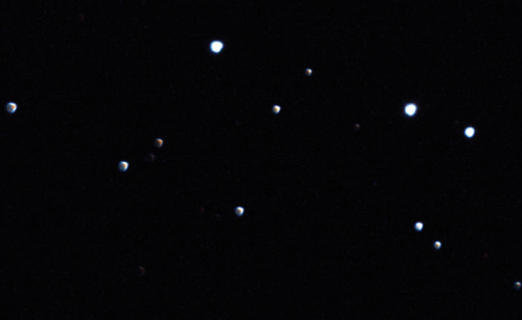
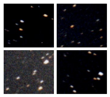
The largest off-axis aberration is coma. It derives its name from the comet-like appearance of the resulting images, as shown in figure 13. At the centre of the focal plane, the images of the stars are point-like. Moving towards the edge of the image, however, the stellar images become increasing comet-like, with the faint, fanned "tail" always pointing away from the centre of the field.
| figure 13: |
An example of coma.
The lower image shows an enlarged view of the bottom left-hand corner
of the upper image.
|
We can understand how coma arises by considering the mirror as a
series of annuli, as shown in figure 14.
If the mirror is used to image an off-axis star, each annulus will
form a separate annular image, or comatic circle, of the star
in the focal plane. Each point on the annular image corresponds to the
meeting of two rays from diametrically opposite points of the
corresponding annulus on the mirror, with smaller mirror annuli
forming smaller comatic circles in the focal plane. The result of these
overlapping comatic circles is a comet-like image like the ones shown
in figure 13. The size of comatic
aberration increases linearly with the angle ![]() between the incoming ray and the optical
axis.
between the incoming ray and the optical
axis.
| figure 14: |
A schematic showing how coma is produced by a parabolic mirror.
|
The next most important off-axis aberration is
astigmatism. Considering rays from just the horizontal and
vertical planes, figure 15 shows how
astigmatism arises: when the rays in the vertical plane are in focus,
the rays in the horizontal plane form a horizontal line. Similarly, at
the point where the rays in the horizontal plane are in focus, the
rays in the vertical plane form a vertical line. (Considering all
other planes would result in an elliptical image, not a line).
Elsewhere the image is elliptical, except at the circle of least
confusion, where the image is circular and at its smallest extent. The
distance between the two line images, and so the size of the circle of
least confusion, is proportional to the square of the off-axis angle
![]() .
.
| figure 15: |
A schematic showing how astigmatism is produced by a parabolic mirror.
|
Astigmatism can easily be recognised in a telescope if the images of off-axis point sources are elliptical, as shown in figure 16. The presence of astigmatism can be confirmed by adjusting the telescope focus, i.e. moving the focal plane, first one way and then the other. The ellipse should turn into a circle and then into an ellipse again on the other side of the best focus, but with its major axis rotated by 90o (as shown in figure 15). It is important not to confuse this aberration, which affects only off-axis images, with the eye defect of the same name, which affects the entire field of vision and is due to a misshapen eye lens.
| figure 16: |
An image of a star showing astigmatism.
|
| figure 17: |
Top: An example of curvature of field. Each image shows a small region at the
four corners of a much wider-field
photograph.
Bottom: An example of distortion of field - two
images of the Milky
Way taken with the same telescope. The two yellow boxes in the top panels
contain the same patch of sky, and their contents are enlarged in the
bottom panels.
|
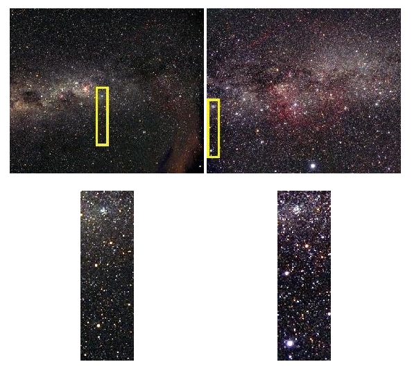
Distortion of field is said to be present when the plate scale varies over the focal plane, as shown in the lower panel of figure 17. The yellow box in the left-hand image is near the field centre. The positions of the two brightest stars in this yellow box should be compared with the positions of the same two stars in the right-hand image, which are now at the field edge. It can be seen that, although the individual stellar images appear aberration-free, their separation is much greater in the right-hand image, i.e. the plate scale is smaller.
Newtonian reflectors
James Gregory was never able to bring his telescope design, known as the Gregorian, into practical use, and it is Isaac Newton who is credited with making the first working reflecting telescope in 1668. His design, known as the Newtonian, is shown in figure 18. The Newtonian is a two-mirror telescope in which the first mirror in the light path, known as the primary, is a concave parabola. The secondary mirror has no curvature at all and is hence referred to as a flat. It simply folds the light through 90o, placing the focal plane just outside the incoming beam. The focal ratio at the Newtonian focus is typically about 5. The secondary mirror is inclined at an angle of 45o with respect to the primary. The base of the flat is actually elliptical in shape so as to minimise the size of the circular shadow it casts on the primary.
| figure 18: |
A schematic of a Newtonian reflector.
|
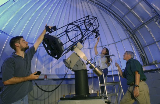
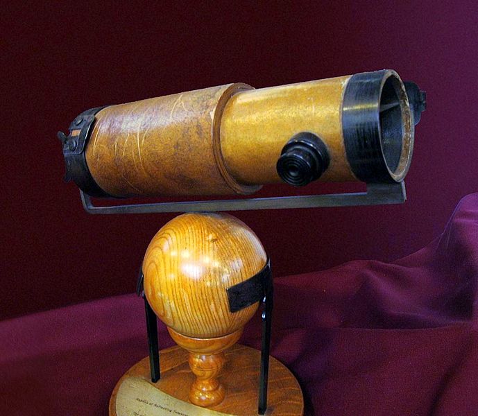
Although small amateur telescopes still adopt a Newtonian configuration, visual access to the focus becomes inconvenient as the telescope becomes larger, and mounting instrumentation there would unbalance the telescope, as demonstrated in the upper panel of figure 19. Hence Newtonians are rarely found in professional observatories.
| figure 19: |
Top: A photograph of a modern Newtonian reflector. Bottom: A replica of Newton's
original reflecting telescope.
|
Cassegrain reflectors
In 1672, the French priest Laurent Cassegrain developed another reflecting telescope design which is now named after him - the Cassegrain. This design, shown in figure 20, has been adopted by the majority of the world's largest telescopes due to the convenience of mounting instrumentation at the focus.
| figure 20: |
A schematic of a Cassegrain reflector.
|
The Cassegrain telescope has a concave parabolic primary mirror like the Newtonian, but it employs a convex hyperboloidal secondary. This increases the focal length of the telescope and reflects the beam back towards the primary, where it passes through a hole bored in the centre of the mirror and comes to a focus just below it. This is a much more easily accessible focus than the Newtonian, and an ideal place to mount large and heavy instrumentation, as shown in figure 21. Compared to a Newtonian, nothing is lost by having a hole in the primary, as this region of the mirror lies under the shadow of the secondary. Moreover, because the beam is folded back on itself, it is possible to have a much longer focal length telescope without a correspondingly long tube: the focal ratio of a typical Cassegrain focus is 15.
| figure 21: |
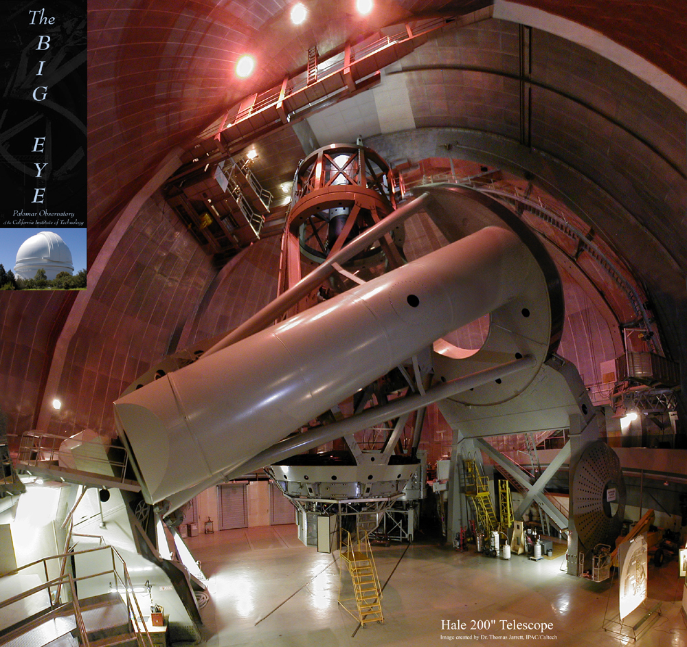
Photograph of the 5m Hale Telescope on Mount Palomar, California.
This telescope is a Cassegrain reflector and was the largest telescope in the
world between 1948 and 1993.
|
Another convenient feature of Cassegrain telescopes is that the focus can be adjusted by moving the secondary mirror towards or away from the primary, allowing the instrumentation to remain fixed in place. In addition, many large research Cassegrains have removable secondary mirrors, giving access to prime focus (see figures 20 and 22). This focus is optically equivalent to the Newtonian, and provides a much smaller focal ratio and hence larger field of view than the Cassegrain focus. The wider field makes prime-focus imaging more susceptible to off-axis aberrations than Cassegrain-focus imaging, hence lens-based correctors are usually required at prime focus.
| figure 22: |
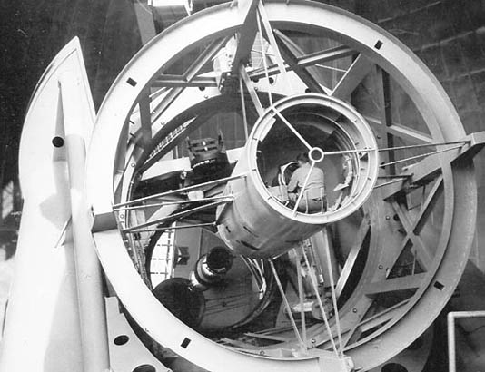
Photograph
of an observer in the prime focus cage of the Hale
telescope. Nowadays, remote operation of prime-focus instrumention
means that it is no longer necessary for astronomers to spend the
night in the cage!
|
Ritchey-Chretien reflectors
Both the Newtonian and Cassegrain telescopes suffer from significant off-axis aberrations, primarily coma. To remedy this, the American and French optical designers George Ritchey and Henri Chretien jointly developed the Ritchey-Chretien telescope around 1910. The Ritchey-Chretien is a modified form of the Cassegrain design, with a concave hyperbolic primary and a convex hyperbolic secondary. The advantage of this design is that both spherical aberration and coma are removed. Astigmatism and field curvature are also reduced, all at the expense of a larger secondary mirror. Hence the Ritchey-Chretien delivers significantly better imaging performance over a wider field of view than a Cassegrain, but with a slightly lower light grasp. It is much more complex to manufacture and test a hyperbolic mirror than a paraboloid, hence the Ritchey-Chretien design tends to be expensive and is found mainly in large research telescopes. The best known example of a Ritchey-Chretien telescope is the 2.4m Hubble Space Telescope, shown in figures 23.
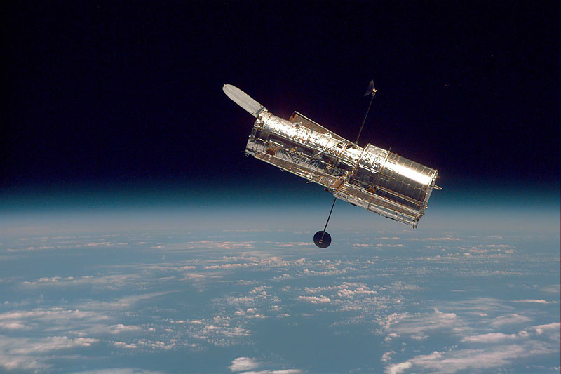
| figure 23: |
Photograph
of the HST, a Ritchey-Chretien telescope.
|